
Packet Flow
| Document revision: | 2.8 (February 11, 2008, 4:14 GMT) |
| Applies to: | V3.0 |
General Information
Summary
This manual describes the order in which an IP packet traverses various internal facilities of the router and some general information regarding packet handling, common IP protocols and protocol options.
Specifications
Packages required: systemLicense required: Level3
Submenu level: /ip firewall
Standards and Technologies: IP
Hardware usage: Increases with NAT, mangle and filter rules count
Packet Flow
Description
MikroTik RouterOS is designed to be easy to operate in various aspects, including IP firewall. Therefore regular firewall policies can be created and deployed without the knowledge about how the packets are processed in the router. For example, if all that required is just natting internal clients to a public address, the following command can be issued (assuming the interface to the Internet is named Public):
/ip firewall nat add action=masquerade out-interface=Public chain=srcnat
Regular packet filtering, bandwith management or packet marking can be configured with ease in a similar manner. However, a more complicated configuration could be deployed only with a good understanding of the underlying processes in the router.
The packet flow through the router is depicted in the following diagram:
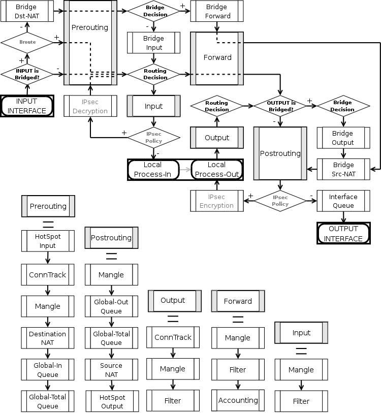
As can be seen on the diagram, there are five chains in the processing pipeline. These are prerouting, input, forward, output and postrouting. The actions performed on a packet in each chain are discussed later in this chapter.
Additional arrows from IPsec boxes shows the processing of encrypted packets (they need to be encrypted / decrypted first and then processed as usual, id est from the point an ordinal packet enters the router).
A packet can enter processing conveyer of the router in two ways. First, a packet can come from one of the interfaces present in the roter (then the interface is referred as input interface). Second, it can be originated from a local process, like web proxy, VPN or others. Alike, there are two ways for a packet to leave the processing pipeline. A packet can leave through the one of the router's interfaces (in this case the interface is referred as output interface) or it can end up in the local process. In general, traffic can be destined to one of the router's IP addresses, it can originate from the router or simply should be passed through. To further complicate things the traffic can be bridged or routed one, which is determined during the Bridge Decision stage.
Routed trafficThe traffic received for the router's MAC address on the respective port, is passed to the routing procedures and can be of one of these four types:
- the traffic which is destined to the router itself. The IP packets has destination address equal to one of the router's own IP addresses. A packet enters the router through the input interface, sequentially traverses prerouting and input chains and ends up in the local process that listens for that particular kind of traffic (if no process is expecting the packet, it is discarded). Consequently, a packet can be filtered in the input chain filter and mangled in two places: the input and the prerouting chain filters.
- the traffic is originated from the router. In this case the IP packets have their source addresses identical to one of the router's IP addresses. If no address is assumed by the sender (either explicitly set by the sending process or, as a reply, is set to the address the request came to), the actual source address is set by the routing process to the preferred address of the respective route. Such packets travel through the output chain, then they are passed to the routing facility where an appropriate routing path for each packet is determined and leave through the postrouting chain.
- routable traffic, which is received at the router's MAC address, has an IP address different from any of the router's own addresses, and its destination can be found in the routing tables. These packets go through the prerouting, forward and postrouting chains.
- unroutable traffic, which is received at the router's MAC address, has an IP address different from any of the router's own addresses, but its destination can not be found in the routing tables. These packets go through the prerouting and stop in the routing recision.
The actions imposed by various router facilities are sequentially applied to a packet in each of the default chains. The exact order they are applied is pictured at the bottom of the flow diagram. Exempli gratia, for a packet passing postrouting chain the mangle rules are applied first, two types of queuing come in second place and finally source NAT is performed on packets that need to be natted.
Note, that any given packet can come through only one of the input, forward or output chains.
Bridged TrafficIn case the incoming traffic needs to be bridged (do not confuse it with the traffic coming to the bridge interface at the router's own MAC address and, thus, classified as routed traffic) it is first determined whether it is an IP traffic or not. After that, IP traffic goes through the prerouting, forward and postrouting chains, while non-IP traffic bypasses all IP firewall rules and goes directly to the interface queue. Both types of traffic, however, undergo the full set of bridge firewall chains anyway, regardless of the protocol.
Connection Tracking
Submenu level: /ip firewall connectionDescription
Connection tracking refers to the ability to maintain the state information about connections, such as source and destination IP address and ports pairs, connection states, protocol types and timeouts. Firewalls that do connection tracking are known as "stateful" and are inherently more secure that those who do only simple "stateless" packet processing.
The state of a particular connection could be estabilished meaning that the packet is part of already known connection, new meaning that the packet starts a new connection or belongs to a connection that has not seen packets in both directions yet, related meaning that the packet starts a new connection, but is associated with an existing connection, such as FTP data transfer or ICMP error message and, finally, invalid meaning that the packet does not belong to any known connection and, at the same time, does not open a valid new connection.
Connection tracking is done in the prerouting chain, or the output chain for locally generated packets.
Another function of connection tracking which cannot be overestimated is that it is needed for NAT. You should be aware that no NAT can be performed unless you have connection tracking enabled, the same applies for p2p protocols recognition. Connection tracking also assembles IP packets from fragments before further processing.
The maximum number of connections the /ip firewall connection state table can contain is determined by the amount of physical memory present in the router.
Please ensure that your router is equipped with sufficient amount of physical memory to properly handle all connections.
Property Description
assured (read-only: true | false) - shows whether replay was seen for the last packet matching this entryconnection-mark (read-only: text) - Connection mark set in mangledst-address (read-only: IP address:port) - the destination address and port the connection is established toicmp-id (read-only: integer) - contains the ICMP ID. Each ICMP packet gets an ID set to it when it is sent, and when the receiver gets the ICMP message, it sets the same ID within the new ICMP message so that the sender will recognize the reply and will be able to connect it with the appropriate ICMP requesticmp-option (read-only: integer) - the ICMP type and code fieldsp2p (read-only: text) - peer to peer protocolprotocol (read-only: text) - IP protocol name or numberreply-dst-address (read-only: IP address:port) - the destination address and port the reply connection is established toreply-icmp-id (read-only: integer) - contains the ICMP ID of received packetreply-icmp-option (read-only: integer) - the ICMP type and code fields of received packetreply-src-address (read-only: IP address:port) - the source address and port the reply connection is established fromsrc-address (read-only: IP address:port) - the source address and port the connection is established fromtcp-state (read-only: text) - the state of TCP connectiontimeout (read-only: time) - the amount of time until the connection will be timed outunreplied (read-only: true | false) - shows whether the request was unrepliedConnection Timeouts
Submenu level: /ip firewall connection trackingDescription
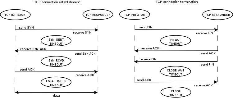
Connection tracking provides several timeouts. When particular timeout expires the according entry is removed from the connection state table. The following diagram depicts typical TCP connection establishment and termination and tcp timeouts that take place during these processes:
Property Description
enable (yes | no; default: yes) - whether to allow or disallow connection trackinggeneric-timeout (time; default: 10m) - maximal amount of time connection state table entry that keeps tracking of packets that are neither TCP nor UDP (for instance GRE) will survive after having seen last packet matching this entry. Creating PPTP connection this value will be increased automaticlyicmp-timeout (time; default: 10s) - maximal amount of time connection tracking entry will survive after having seen ICMP requestmax-entries (read-only: integer) - the maximum number of connections the connection state table can contain, depends on an amount of total memorytcp-close-timeout (time; default: 10s) - maximal amount of time connection tracking entry will survive after having seen connection reset request (RST) or an acknowledgment (ACK) of the connection termination request from connection release initiatortcp-close-wait-timeout (time; default: 10s) - maximal amount of time connection tracking entry will survive after having seen an termination request (FIN) from respondertcp-established-timeout (time; default: 1d) - maximal amount of time connection tracking entry will survive after having seen an acknowledgment (ACK) from connection initiatortcp-fin-wait-timeout (time; default: 10s) - maximal amount of time connection tracking entry will survive after having seen connection termination request (FIN) from connection release initiatortcp-syn-received-timeout (time; default: 1m) - maximal amount of time connection tracking entry will survive after having seen a matching connection request (SYN)tcp-syn-sent-timeout (time; default: 1m) - maximal amount of time connection tracking entry will survive after having seen a connection request (SYN) from connection initiatortcp-syncookie (yes | no; default: no) - enable TCP SYN cookies for connections destined to the router itself (this may be useful for HotSpot and tunnels)tcp-time-wait-timeout (time; default: 10s) - maximal amount of time connection tracking entry will survive after having seen connection termination request (FIN) just after connection request (SYN) or having seen another termination request (FIN) from connection release initiatortotal-entries (read-only: integer) - number of connections currently recorded in the connection state tableudp-stream-timeout (time; default: 3m) - maximal amount of time connection tracking entry will survive after replay is seen for the last packet matching this entry (connection tracking entry is assured). It is used to increase timeout for such connections as H323, VoIP, etc.udp-timeout (time; default: 10s) - maximal amount of time connection tracking entry will survive after having seen last packet matching this entryNotes
The maximum timeout value depends on amount of entries in connection state table. If amount of entries in the table is more than:
- 1/16 of maximum number of entries the maximum timeout value will be 1 day
- 3/16 of maximum number of entries the maximum timeout value will be 1 hour
- 1/2 of maximum number of entries the maximum timeout value will be 10 minute
- 13/16 of maximum number of entries the maximum timeout value will be 1 minute
The shortest timeout will always be chosen between the configured timeout and the value listed above.
If connection tracking timeout value is less than the normal interval between the data packets rate (timeout expires before the next packet arives), NAT and statefull-firewalling stop working.
Service Ports
Submenu level: /ip firewall service-portDescription
Some network protocols are not compatible with network address translation, for example due to some additional infomation about the actual addresses or ports is present in the packet payload, which is not known for the NAT procedures, as they only look at the IP, UDP and TCP headers, not inside the packets. For these protocols to work correctly, a connection tracking helper is needed to work around such design issues. You may enable and disable helpers here (you may want to disable some of them to increase performance or if you are experiencing problems with some protocols detected incorrectly). Note that you can not add or remove the helpers, just enable or disable the existing ones.
Property Description
name - protocol nameports (integer) - port range that is used by the protocol (only some helpers need this)General Firewall Information
Description
ICMP TYPE:CODE valuesIn order to protect your router and attached private networks, you need to configure firewall to drop or reject most of ICMP traffic. However, some ICMP packets are vital to maintain network reliability or provide troubleshooting services.
The following is a list of ICMP TYPE:CODE values found in good packets. It is generally suggested to allow these types of ICMP traffic.
- 8:0 - echo request
- 0:0 - echo reply
- 11:0 - TTL exceeded
- 3:3 - Port unreachable
- 3:4 - Fragmentation-DF-Set
Ping
Trace
Path MTU discovery
General suggestion to apply ICMP filtering
- Allow ping—ICMP Echo-Request outbound and Echo-Reply messages inbound
- Allow traceroute—TTL-Exceeded and Port-Unreachable messages inbound
- Allow path MTU—ICMP Fragmentation-DF-Set messages inbound
- Block everything else
Peer-to-peer protocols also known as p2p provide means for direct distributed data transfer between individual network hosts. While this technology powers many brilliant applications (like Skype), it is widely abused for unlicensed software and media destribution. Even when it is used for legal purposes, p2p may heavily disturb other network traffic, such as http and e-mail. RouterOS is able to recognize connections of the most popular P2P protocols and filter or enforce QOS on them.
The protocols which can be detected, are:
- Fasttrack (Kazaa, KazaaLite, Diet Kazaa, Grokster, iMesh, giFT, Poisoned, mlMac)
- Gnutella (Shareaza, XoLoX, , Gnucleus, BearShare, LimeWire (java), Morpheus, Phex, Swapper, Gtk-Gnutella (linux), Mutella (linux), Qtella (linux), MLDonkey, Acquisition (Mac OS), Poisoned, Swapper, Shareaza, XoloX, mlMac)
- Gnutella2 (Shareaza, MLDonkey, Gnucleus, Morpheus, Adagio, mlMac)
- DirectConnect (DirectConnect (AKA DC++), MLDonkey, NeoModus Direct Connect, BCDC++, CZDC++ )
- eDonkey (eDonkey2000, eMule, xMule (linux), Shareaza, MLDonkey, mlMac, Overnet)
- Soulseek (Soulseek, MLDonkey)
- BitTorrent (BitTorrent, BitTorrent++, uTorrent, Shareaza, MLDonkey, ABC, Azureus, BitAnarch, SimpleBT, BitTorrent.Net, mlMac)
- Blubster (Blubster, Piolet)
- WPNP (WinMX)
- Warez (Warez, Ares; starting from 2.8.18) - this protocol can only be dropped, speed limiting is impossible