
LCD Management
| Document revision: | 2.5 (July 9, 2007, 9:36 GMT) |
| Applies to: | V2.9 |
General Information
Summary
LCDs are used to display system information.
The MikroTik RouterOS supports the following LCD hardware:
- Crystalfontz (http://www.crystalfontz.com) Intelligent Serial LCD Module 632 (16x2 characters) and 634 (20x4 characters)
- Powertip (http://www.powertip.com.tw) PC1602 (16x2 characters), PC1604 (16x4 characters), PC2002 (20x2 characters), PC2004 (20x4 characters), PC2402 (24x2 characters) and PC2404 (24x4 characters)
- Portwell (http://www.portwell.com.tw) EZIO-100 (16x2 characters)
Specifications
Packages required: lcdLicense required: Level1
Submenu level: /system lcd
Standards and Technologies: None
Hardware usage: Not significant
Related Documents
Description
How to Connect PowerTip LCD to a Parallel PortData signals are connected that way:
| DB25m | Signal | LCD Panel |
| 1 | Enable (Strobe) | 6 |
| 2 | Data 0 | 7 |
| 3 | Data 1 | 8 |
| 4 | Data 2 | 9 |
| 5 | Data 3 | 10 |
| 6 | Data 4 | 11 |
| 7 | Data 5 | 12 |
| 8 | Data 6 | 13 |
| 9 | Data 7 | 14 |
| 14 | Register Select | 4 |
| 18-25, GND | Ground | 1, 5, 16 |
Powering:
As there are only 16 pins for the PC1602 modules, you need not connect power to the 17th pin.
GND and +5V can be taken from computer's internal power supply (use black wire for GND and red wire for +5V)
WARNING! Be very careful connecting power supply. We do not recommend using external power supplies. In no event shall MikroTik liable for any hardware damages.
Note that there are some PowerTip PC2404A modules that have different pin-out. Compare:
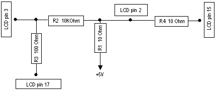
Some LCDs may be connected without resistors:
| DB25m | Signal | LCD Panel |
| 18-25, GND | Ground | 1, 3, 4, 16 |
| +5V | Power | 2, 15 |
Before connecting the LCD, please check the availability of ports, their configuration, and free the desired port resource, if required:
[admin@MikroTik] port> print
  # NAME			     USED-BY			      BAUD-RATE
  0 serial0			     Serial Console		      9600
  1 serial1							      9600
[admin@MikroTik] port>
The baud rate should be set to 9600 for use with the Crystalfontz serial LCD modules.
Portwell Installation NotesThe baud rate should be set to 2400 for Portwell LCD modules. The flow control should be set to none. Make sure you use V2.9.44 or later of RouterOS. The wiring for the DB9 to 10-pin female header cable is:
| DB9 female | 10-pin female header |
| 2 | 2 |
| 3 | 3 |
| 5 | 5 |
Please note that the actual traces may not correspond to any of the documents coming from the manufacturer. It seems that all pin numbers of J2 are printed on the silkscreen in a "mirrored" way. Thus, the #1 pin is where the "5" is printed (the wiring above lists actual pin numbers, not the ones printed on the board).
Configuring the LCD's Settings
Submenu level: /system lcdProperty Description
contrast (integer: 0..255; default: 0) - contrast setting, sent to the LCD, if it supports contrast regulationsenabled (yes | no; default: no) - turns the LCD on or offport (name | parallel; default: parallel) - name of the port where the LCD is connected. May be either one of the serial ports, or the first paralleltype (16x2 | 16x4 | 20x2 | 20x4 | 24x2 | 24x4 | mtb-134; default: 24x4) - sets the type of the LCDExample
To enable Powertip parallel port LCD:
[admin@MikroTik] system lcd> print
   enabled: no
      type: 24x4
      port: parallel
  contrast: 0
[admin@MikroTik] system lcd> set enabled=yes
[admin@MikroTik] system lcd> print
   enabled: yes
      type: 24x4
      port: parallel
  contrast: 0
[admin@MikroTik] system lcd>
To enable Crystalfontz serial LCD on serial1:
[admin@MikroTik] system lcd> set port=serial1
[admin@MikroTik] system lcd> print
   enabled: yes
      type: 24x4
      port: serial1
  contrast: 0
[admin@MikroTik] system lcd>
LCD Information Display Configuration
Submenu level: /system lcd pageDescription
The submenu is used for configuring LCD information display: what pages and how long will be shown.
Property Description
description (read-only: text) - page descriptiondisplay-time (time; default: 5s) - how long to display the pageNotes
You cannot neither add your own pages (they are created dynamically depending on the configuration) nor change pages' description.
Example
To enable displaying all the pages:
[admin@MikroTik] system lcd page> print
Flags: X - disabled
  #   DISPLAY-TIME	   DESCRIPTION
  0 X 5s		   System date and time
  1 X 5s		   System resources - cpu and memory load
  2 X 5s		   System uptime
  3 X 5s		   Aggregate traffic in packets/sec
  4 X 5s		   Aggregate traffic in bits/sec
  5 X 5s		   Software version and build info
  6 X 5s		   ether1
  7 X 5s		   prism1
[admin@MikroTik] system lcd page> enable [find]
[admin@MikroTik] system lcd page> print
Flags: X - disabled
  #   DISPLAY-TIME	   DESCRIPTION
  0   5s		   System date and time
  1   5s		   System resources - cpu and memory load
  2   5s		   System uptime
  3   5s		   Aggregate traffic in packets/sec
  4   5s		   Aggregate traffic in bits/sec
  5   5s		   Software version and build info
  6   5s		   ether1
  7   5s		   prism1
[admin@MikroTik] system lcd page>
To set "System date and time" page to be displayed for 10 seconds:
[admin@MikroTik] system lcd page> set 0 display-time=10s
[admin@MikroTik] system lcd page> print
Flags: X - disabled
  #   DISPLAY-TIME	   DESCRIPTION
  0   10s		   System date and time
  1   5s		   System resources - cpu and memory load
  2   5s		   System uptime
  3   5s		   Aggregate traffic in packets/sec
  4   5s		   Aggregate traffic in bits/sec
  5   5s		   Software version and build info
  6   5s		   ether1
  7   5s		   prism1
[admin@MikroTik] system lcd page>
LCD Troubleshooting
Description
LCD doesn't work, cannot be enabled by the '/system lcd set enabled=yes' command.
Probably the selected serial port is used by PPP client or server, or by the serial console. Check the availability and use of the ports by examining the output of the /port print command. Alternatively, select another port for connecting the LCD, or free up the desired port by disabling the related resource
LCD doesn't work, does not show any information.
Probably none of the information display items have been enabled. Use the /system lcd page set command to enable the display.