
OSPF
| Document revision: | 1.4 (Wed Dec 21 17:26:39 GMT 2005) |
| Applies to: | V2.9 |
General Information
Summary
MikroTik RouterOS implements OSPF Version 2 (RFC 2328). The OSPF protocol is the link-state protocol that takes care of the routes in the dynamic network structure that can employ different paths to its subnetworks. It always chooses shortest path to the subnetwork first.
Specifications
Packages required: routingLicense required: Level3
Submenu level: /routing ospf
Standards and Technologies: OSPF
Hardware usage: Not significant
Related Documents
Description
Open Shortest Path First protocol is a link-state routing protocol. It's uses a link-state algorithm to build and calculate the shortest path to all known destinations. The shortest path is calculated using the Dijkstra algorithm. OSPF distributes routing information between the routers belonging to a single autonomous system (AS). An AS is a group of routers exchanging routing information via a common routing protocol.
In order to deploy the OSPF all routers it will be running on should be configured in a coordinated manner (note that it also means that the routers should have the same MTU for all the networks advertized by OSPF protocol).
The OSPF protocol is started after you will add a record to the OSPF network list. The routes learned by the OSPF protocol are installed in the routes table list with the distance of 110.
General Setup
Submenu level: /routing ospfDescription
In this section you will learn how to configure basic OSPF settings.
Property Description
distribute-default (never | if-installed-as-type-1 | if-installed-as-type-2 | always-as-type-1 | always-as-type-2; default: never) - specifies how to distribute default route. Should be used for ABR (Area Border router) or ASBR (Autonomous System boundary router) settingsif-installed-as-type-1 - send the default route with type 1 metric only if it has been installed (a static default route, or route added by DHCP, PPP, etc.)
if-installed-as-type-2 - send the default route with type 2 metric only if it has been installed (a static default route, or route added by DHCP, PPP, etc.)
always-as-type-1 - always send the default route with type 1 metric
always-as-type-2 - always send the default route with type 2 metric
Notes
Within one area, only the router that is connected to another area (i.e. Area border router) or to another AS (i.e. Autonomous System boundary router) should have the propagation of the default route enabled.
OSPF protocol will try to use the shortest path (path with the smallest total cost) if available.
OSPF protocol supports two types of metrics:
- type1 - external metrics are expressed in the same units as OSPF interface cost. In other words the router expects the cost of a link to a network which is external to AS to be the same order of magnitude as the cost of the internal links.
- type2 - external metrics are an order of magnitude larger; any type2 metric is considered greater than the cost of any path internal to the AS. Use of type2 external metric assumes that routing between AS is the major cost of routing a packet, and climinates the need conversion of external costs to internal link state metrics.
Both Type 1 and Type 2 external metrics can be used in the AS at the same time. In that event, Type 1 external metrics always take precedence.
In /ip route you can see routes with Io status. Because router receives routers from itself.
The metric cost can be calculated from line speed by using the formula 10e+8/line speed. The table contains some examples:
| network type | cost | |
| ethernet | 10 | |
| T1 | 64 | |
| 64kb/s | 1562 | |
Example
To enable the OSPF protocol redisrtibute routes to the connected networks as type1 metrics with the cost of 1, you need do the following:
[admin@MikroTik] routing ospf> set redistribute-connected=as-type-1 \
\... metric-connected=1
[admin@MikroTik] routing ospf> print
                 router-id: 0.0.0.0
        distribute-default: never
    redistribute-connected: as-type-1
       redistribute-static: no
          redistribute-rip: no
          redistribute-bgp: no
            metric-default: 1
          metric-connected: 1
             metric-static: 20
                metric-rip: 20
                metric-bgp: 20
[admin@MikroTik] routing ospf>
Areas
Submenu level: /routing ospf areaDescription
OSPF allows collections of routers to be grouped together. Such group is called an area. Each area runs a separate copy of the basic link-state routing algorithm. This means that each area has its own link-state database and corresponding graph
The structure of an area is invisible from the outside of the area. This isolation of knowledge enables the protocol to effect a marked reduction in routing traffic as compared to treating the entire Autonomous System as a single link-state domain
60-80 routers have to be the maximum in one area
Property Description
area-id (IP address; default: 0.0.0.0) - OSPF area identifier. Default area-id=0.0.0.0 is the backbone area. The OSPF backbone always contains all area border routers. The backbone is responsible for distributing routing information between non-backbone areas. The backbone must be contiguous. However, areas do not need to be physical connected to backbone. It can be done with virtual link. The name and area-id for this area can not be changedauthetication (none | simple | md5; default: none) - specifies authentication method for OSPF protocol messagessimple - plain text authentication
md5 - keyed Message Digest 5 authentication
Example
To define additional OSPF area named local_10 with area-id=0.0.10.5, do the following:
[admin@WiFi] routing ospf area> add area-id=0.0.10.5 name=local_10
[admin@WiFi] routing ospf area> print
Flags: X - disabled, I - invalid
 #   NAME                      AREA-ID         STUB DEFAULT-COST AUTHENTICATION
 0   backbone                  0.0.0.0                           none
 1   local_10                  0.0.10.5        no   1            none
[admin@WiFi] routing ospf area>
Networks
Submenu level: /routing ospf networkDescription
There can be Point-to-Point networks or Multi-Access networks. Multi-Access network can be a broadcast network (a single message can be sent to all routers)
To start the OSPF protocol, you have to define the networks on which it will run and the area ID for each of those networks
Property Description
area (name; default: backbone) - the OSPF area to be associated with the specified address rangenetwork (IP address mask; default: 20) - the network associated with the area. The network argument allows defining one or multiple interfaces to be associated with a specific OSPF area. Only directly connected networks of the router may be specifiedNotes
You should set the network address exactly the same as the remote point IP address for point-to-point links. The right netmask in this case is /32.
Example
To enable the OSPF protocol on the 10.10.1.0/24 network, and include it into the backbone area, do the following:
[admin@MikroTik] routing ospf network> add area=backbone network=10.10.1.0/24
[admin@MikroTik] routing ospf network> print
Flags: X - disabled
  #   NETWORK            AREA
  0   10.10.1.0/24       backbone
[admin@MikroTik] routing ospf>
Interfaces
Submenu level: /routing ospf interfaceDescription
This facility provides tools for additional in-depth configuration of OSPF interface specific parameters. You do not have to configure interfaces in order to run OSPF
Property Description
authentication-key (text; default: "") - authentication key have to be used by neighboring routers that are using OSPF's simple password authenticationcost (integer: 1..65535; default: 1) - interface cost expressed as link state metricdead-interval (time; default: 40s) - specifies the interval after which a neighbor is declared as dead. The interval is advertised in the router's hello packets. This value must be the same for all routers and access servers on a specific networkhello-interval (time; default: 10s) - the interval between hello packets that the router sends on the interface. The smaller the hello-interval, the faster topological changes will be detected, but more routing traffic will ensue. This value must be the same on each end of the adjancency otherwise the adjacency will not forminterface (name; default: all) - interface on which OSPF will runExample
To add an entry that specifies that ether2 interface should send Hello packets every 5 seconds, do the following:
[admin@MikroTik] routing ospf> interface add interface=ether2 hello-interval=5s
[admin@MikroTik] routing ospf> interface print
  0 interface=ether2 cost=1 priority=1 authentication-key=""
    retransmit-interval=5s transmit-delay=1s hello-interval=5s
    dead-interval=40s


[admin@MikroTik] routing ospf>
Virtual Links
Submenu level: /routing ospf virtual-linkDescription
As stated in OSPF RFC, the backbone area must be contiguous. However, it is possible to define areas in such a way that the backbone is no longer contiguous. In this case the system administrator must restore backbone connectivity by configuring virtual links. Virtual link can be configured between two routers through common area called transit area, one of them should have to be connected with backbone. Virtual links belong to the backbone. The protocol treats two routers joined by a virtual link as if they were connected by an unnumbered point-to-point network
Property Description
neighbor-id (IP address; default: 0.0.0.0) - specifies router-id of the neighbourtransit-area (name; default: (unknown)) - a non-backbone area the two routers have in commonNotes
Virtual links can not be estabilished through stub areas
Example
To add a virtual link with the 10.0.0.201 router through the ex area, do the following:
[admin@MikroTik] routing ospf virtual-link> add neighbor-id=10.0.0.201 \
\... transit-area=ex
[admin@MikroTik] routing ospf virtual-link> print
Flags: X - disabled, I - invalid
  #   NEIGHBOR-ID     TRANSIT-AREA
  0   10.0.0.201      ex
[admin@MikroTik] routing ospf virtual-link>
Virtual link should be configured on both routers
Neighbours
Submenu level: /routing ospf neigborDescription
The submenu provides an access to the list of OSPF neighbors, id est the routers adjacent to the current router, and supplies brief statistics
Property Description
address (read-only: IP address) - appropriate IP address of the neighbourbackup-dr-id (read-only: IP address) - backup designated router's router id for this neighbordb-summaries (read-only: integer) - number of records in link-state database advertised by the neighbourdr-id (read-only: IP address) - designated router's router id for this neighborls-requests (read-only: integer) - number of link-state requestsls-retransmits (read-only: integer) - number of link-state retransmitspriority (read-only: integer) - the priority of the neigbour which is used in designated router elections via Hello protocol on this networkrouter-id (read-only: IP address) - the router-id parameter of the neighbourstate (read-only: Down | Attempt | Init | 2-Way | ExStart | Exchange | Loading | Full) - the state of the connection:Attempt - the router is sending Hello protocol packets
Init - Hello packets are exchanged between routers to create a Neighbour Relationship
2-Way - the routers add each other to their Neighbour database and they become neighbours
ExStart - the DR (Designated Router) and BDR (Backup Designated Router) create an adjancency with each other and they begin creating their link-state databases using Database Description Packets
Exchange - is the process of discovering routes by exchanging Database Description Packets
Loading - receiving information from the neighbour
Full - the link-state databases are completely synchronized. The routers are routing traffic and continue sending each other hello packets to maintain the adjacency and the routing information
Notes
The neighbour's list also displays the router itself with 2-Way state
Example
The following text can be observed just after adding an OSPF network:
admin@MikroTik] routing ospf> neighbor print
 router-id=10.0.0.204 address=10.0.0.204 priority=1 state="2-Way"
    state-changes=0 ls-retransmits=0 ls-requests=0 db-summaries=0
    dr-id=0.0.0.0 backup-dr-id=0.0.0.0

[admin@MikroTik] routing ospf>
Application Examples
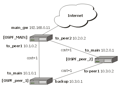
OSPF backup without using a tunnel
Let us assume that the link between the routers OSPF-Main and OSPF-peer-1 is the main one. If it goes down, we want the traffic switch over to the link going through the router OSPF-peer-2.
This example shows how to use OSPF for backup purposes, if you are controlling all the involved routers, and you can run OSPF on them
For this:
- We introduce an OSPF area with area ID=0.0.0.1, which includes all three routers shown on the diagram
- Only the OSPF-Main router will have the default route configured. Its interfaces peer1 and peer2 will be configured for the OSPF protocol. The interface main_gw will not be used for distributing the OSPF routing information
- The routers OSPF-peer-1 and OSPF-peer-2 will distribute their connected route information, and receive the default route using the OSPF protocol
Now let's setup the OSPF_MAIN router.
The router should have 3 NICs:
[admin@OSPF_MAIN] interface> print
Flags: X - disabled, D - dynamic, R - running
  #      NAME                                     TYPE                   RX-RATE      TX-RATE      MTU
  0   R main_gw                                   ether                    0            0          1500
  1   R to_peer_1                                 ether                    0            0          1500
  2   R to_peer_2                                 ether                    0            0          1500
Add all needed ip addresses to interfaces as it is shown here:
[admin@OSPF_MAIN] ip address> print
Flags: X - disabled, I - invalid, D - dynamic
  #    ADDRESS                  NETWORK             BROADCAST          INTERFACE
  0    192.168.0.11/24        192.168.0.0         192.168.0.255      main_gw
  1    10.1.0.2/24            10.1.0.0            10.1.0.255         to_peer_1
  2    10.2.0.2/24            10.2.0.0            10.2.0.255         to_peer_2
You should set distribute-default as if-installed-as-type-2, redistribute-connected as as-type-1 and redistribute-static as as-type-2. Metric-connected, metric-static, metric-rip, metric-bgp should be zero
[admin@OSPF_MAIN] routing ospf> print
                          router-id: 0.0.0.0
                 distribute-default: if-installed-as-type-2
             redistribute-connected: as-type-1
                redistribute-static: as-type-2
                   redistribute-rip: no
                   redistribute-bgp: no
                     metric-default: 1
                   metric-connected: 0
                      metric-static: 0
                         metric-rip: 0
                         metric-bgp: 0
Define new OSPF area named local_10 with area-id 0.0.0.1:
[admin@OSPF_MAIN] routing ospf area> print
Flags: X - disabled, I - invalid
  #    NAME                                 AREA-ID             STUB DEFAULT-COST AUTHENTICATION
  0    backbone                             0.0.0.0                                   none
  1    local_10                             0.0.0.1              no         1         none
Add connected networks with area local_10 in ospf network:
[admin@OSPF_MAIN] routing ospf network> print
Flags: X - disabled, I - invalid
  #    NETWORK                  AREA
  0    10.1.0.0/24            local_10
  1    10.2.0.0/24            local_10
For main router the configuration is done. Next, you should configure OSPF_peer_1 router
Enable followong interfaces on OSPF_peer_1:
[admin@OSPF_peer_1] interface> print
Flags: X - disabled, D - dynamic, R - running
  #      NAME                                     TYPE                   RX-RATE      TX-RATE      MTU
  0   R backup                                    ether                    0             0         1500
  1   R to_main                                   ether                    0             0         1500
Assign IP addresses to these interfaces:
[admin@OSPF_peer_1] ip address> print
Flags: X - disabled, I - invalid, D - dynamic
  #    ADDRESS                  NETWORK             BROADCAST          INTERFACE
  0    10.1.0.1/24              10.1.0.0            10.1.0.255         to_main
  1    10.3.0.1/24              10.3.0.0            10.3.0.255         backup
Set redistribute-connected as as-type-1. Metric-connected, metric-static, metric-rip, metric-bgp should be zero.
[admin@OSPF_peer_1] routing ospf> print
                          router-id: 0.0.0.0
                 distribute-default: never
             redistribute-connected: as-type-1
                redistribute-static: no
                   redistribute-rip: no
                   redistribute-bgp: no
                     metric-default: 1
                   metric-connected: 0
                      metric-static: 0
                         metric-rip: 0
                         metric-bgp: 0
Add the same area as in main router:
[admin@OSPF_peer_1] routing ospf area> print
Flags: X - disabled, I - invalid
  #    NAME                                 AREA-ID             STUB DEFAULT-COST AUTHENTICATION
  0    backbone                             0.0.0.0                                  none
  1    local_10                             0.0.0.1              no         1        none
Add connected networks with area local_10:
[admin@OSPF_peer_1] routing ospf network> print
Flags: X - disabled, I - invalid
  #    NETWORK                  AREA
  0    10.3.0.0/24            local_10
  1    10.1.0.0/24            local_10
Finally, set up the OSPF_peer_2 router. Enable the following interfaces:
[admin@OSPF_peer_2] interface> print
Flags: X - disabled, D - dynamic, R - running
  #      NAME                                     TYPE                   RX-RATE      TX-RATE      MTU
  0   R to_main                                   ether                    0            0         1500
  1   R to_peer_1                                 ether                    0            0         1500
Add the needed IP addresses:
[admin@OSPF_peer_2] ip address> print
Flags: X - disabled, I - invalid, D - dynamic
  #    ADDRESS                  NETWORK             BROADCAST          INTERFACE
  0    10.2.0.1/24              10.2.0.0            10.2.0.255         to_main
  1    10.3.0.2/24              10.3.0.0            10.3.0.255         to_peer_1
Add the same area as in previous routers:
[admin@OSPF_peer_2] routing ospf area> print
Flags: X - disabled, I - invalid
  #    NAME                                 AREA-ID             STUB DEFAULT-COST AUTHENTICATION
  0    backbone                             0.0.0.0                                    none
  1    local_10                             0.0.0.1              no         1          none
Add connected networks with the same area:
[admin@OSPF_peer_2] routing ospf network> print
Flags: X - disabled, I - invalid
  #    NETWORK                  AREA
  0    10.2.0.0/24            local_10
  1    10.3.0.0/24            local_10
After all routers have been set up as described above, and the links between them are operational, the routing tables of the three routers look as follows:
[admin@OSPF_MAIN] ip route> print
Flags: X - disabled, I - invalid, D - dynamic, J - rejected,
C - connect, S - static, r - rip, o - ospf, b - bgp
  #      DST-ADDRESS            G GATEWAY             DISTANCE INTERFACE
  0 Io 192.168.0.0/24				       110
  1 DC 192.168.0.0/24         r 0.0.0.0                0        main_gw
  2 Do 10.3.0.0/24            r 10.2.0.1               110      to_peer_2
                              r 10.1.0.1                        to_peer_1
  3 Io 10.2.0.0/24				       110
  4 DC 10.2.0.0/24            r 0.0.0.0                0        to_peer_2
  5 Io 10.1.0.0/24				       110
  6 DC 10.1.0.0/24            r 0.0.0.0                0        to_peer_1
[admin@OSPF_peer_1] ip route> print
Flags: X - disabled, I - invalid, D - dynamic, J - rejected,
C - connect, S - static, r - rip, o - ospf, b - bgp
  #      DST-ADDRESS            G GATEWAY             DISTANCE INTERFACE
  0 Do 192.168.0.0/24         r 10.1.0.2               110      to_main
  1 Io 10.3.0.0/24				       110
  2 DC 10.3.0.0/24            r 0.0.0.0                0        backup
  3 Do 10.2.0.0/24            r 10.1.0.2               110      to_main
                              r 10.3.0.2                        backup
  4 Io 10.1.0.0/24				       110
  5 DC 10.1.0.0/24            r 0.0.0.0                0        to_main
[admin@OSPF_peer_2] ip route> print
Flags: X - disabled, I - invalid, D - dynamic, J - rejected,
C - connect, S - static, r - rip, o - ospf, b - bgp
  #      DST-ADDRESS            G GATEWAY             DISTANCE INTERFACE
  0 Do 192.168.0.0/24         r 10.2.0.2                110     to_main
  1 Io 10.3.0.0/24  				        110
  2 DC 10.3.0.0/24            r 0.0.0.0                 0       to_peer_1
  3 Io 10.2.0.0/24				        110
  4 DC 10.2.0.0/24            r 0.0.0.0                 0       to_main
  5 Do 10.1.0.0/24            r 10.3.0.1                110     to_peer_1
                              r 10.2.0.2                        to_main
Routing tables with Revised Link Cost
This example shows how to set up link cost. Let us assume, that the link between the routers OSPF_peer_1 and OSPF_peer_2 has a higher cost (might be slower, we have to pay more for the traffic through it, etc.).
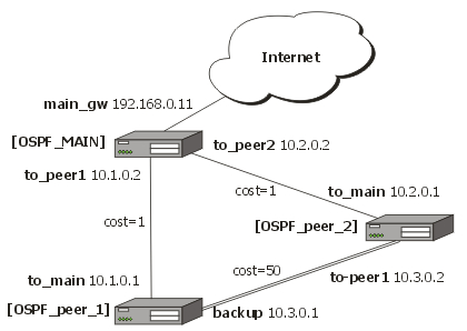
We should change cost value in both routers: OSPF_peer_1 and OSPF_peer_2 to 50. To do this, we need to add a following interface:
[admin@OSPF_peer_1] routing ospf interface> add interface=backup cost=50
[admin@OSPF_peer_1] routing ospf interface> print
  0 interface=backup cost=50 priority=1 authentication-key=""
 retransmit-interval=5s transmit-delay=1s hello-interval=10s
dead-interval=40s

[admin@OSPF_peer_2] routing ospf interface> add interface=to_peer_1 cost=50
[admin@OSPF_peer_2] routing ospf interface> print
  0 interface=to_peer_1 cost=50 priority=1 authentication-key=""
 retransmit-interval=5s transmit-delay=1s hello-interval=10s
     dead-interval=40s
After changing the cost settings, we have only one equal cost multipath route left - to the network 10.3.0.0/24 from OSPF_MAIN router.
Routes on OSPF_MAIN router:
[admin@OSPF_MAIN] ip route> print
Flags: X - disabled, I - invalid, D - dynamic, J - rejected,
C - connect, S - static, r - rip, o - ospf, b - bgp
  #      DST-ADDRESS            G GATEWAY             DISTANCE INTERFACE
  0 Io 192.168.0.0/24				        110
  1 DC 192.168.0.0/24         r 0.0.0.0                 0       main_gw
  2 Do 10.3.0.0/24            r 10.2.0.1                110     to_peer_2
                              r 10.1.0.1                        to_peer_1
  3 Io 10.2.0.0/24				        110
  4 DC 10.2.0.0/24            r 0.0.0.0                 0       to_peer_2
  5 Io 10.1.0.0/24				        110
  6 DC 10.1.0.0/24            r 0.0.0.0                 0       to_peer_1
On OSPF_peer_1:
[admin@OSPF_peer_1] > ip route pr
Flags: X - disabled, I - invalid, D - dynamic, J - rejected,
C - connect, S - static, r - rip, o - ospf, b - bgp
  #      DST-ADDRESS            G GATEWAY             DISTANCE INTERFACE
  0 Do 192.168.0.0/24         r 10.1.0.2               110       to_main
  1 Io 10.3.0.0/24				       110
  2 DC 10.3.0.0/24            r 0.0.0.0                0         backup

  3 Do 10.2.0.0/24            r 10.1.0.2               110       to_main
  4 Io 10.1.0.0/24				       110
  5 DC 10.1.0.0/24            r 0.0.0.0                0         to_main
On OSPF_peer_2:
[admin@OSPF_peer_2] > ip route print
Flags: X - disabled, I - invalid, D - dynamic, J - rejected,
C - connect, S - static, r - rip, o - ospf, b - bgp
  #      DST-ADDRESS            G GATEWAY             DISTANCE INTERFACE
  0 Do 192.168.0.0/24         r 10.2.0.2               110       to_main
  1 Io 10.3.0.0/24				       110
  2 DC 10.3.0.0/24            r 0.0.0.0                0         to_peer_1
  3 Io 10.2.0.0/24				       110
  4 DC 10.2.0.0/24            r 0.0.0.0                0         to_main
  5 Do 10.1.0.0/24            r 10.2.0.2               110       to_main
Functioning of the Backup
If the link between routers OSPF_MAIN and OSPF_peer_1 goes down, we have the following situation:
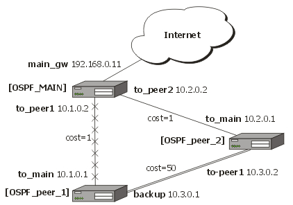
The OSPF routing changes as follows:
Routes on OSPF_MAIN router:
[admin@OSPF_MAIN] ip route> print
Flags: X - disabled, I - invalid, D - dynamic, J - rejected,
C - connect, S - static, r - rip, o - ospf, b - bgp
  #      DST-ADDRESS            G GATEWAY             DISTANCE INTERFACE
  0 Io 192.168.0.0/24				        110
  1 DC 192.168.0.0/24         r 0.0.0.0                 0         main_gw
  2 Do 10.3.0.0/24            r 10.2.0.1                110       to_peer_2
  3 Io 10.2.0.0/24				        110
  4 DC 10.2.0.0/24            r 0.0.0.0                 0         to_peer_2
  5 Io 10.1.0.0/24				        110
  6 DC 10.1.0.0/24            r 0.0.0.0                 0         to_peer_1
On OSPF_peer_1:
[admin@OSPF_peer_1] ip route> print
Flags: X - disabled, I - invalid, D - dynamic, J - rejected,
C - connect, S - static, r - rip, o - ospf, b - bgp
  #      DST-ADDRESS            G GATEWAY             DISTANCE INTERFACE
  0 Do 192.168.0.0/24         r 10.3.0.2                110       backup
  1 Io 192.168.0.0/24				        110
  2 DC 10.3.0.0/24            r 0.0.0.0                 0         backup
  3 Do 10.2.0.0/24            r 10.3.0.2                110       backup
  4 Io 10.1.0.0/24				        110
  5 DC 10.1.0.0/24            r 0.0.0.0                 0         to_main
On OSPF_peer_2:
[admin@OSPF_peer_2] ip route> print
Flags: X - disabled, I - invalid, D - dynamic, J - rejected,
C - connect, S - static, r - rip, o - ospf, b - bgp
  #      DST-ADDRESS            G GATEWAY             DISTANCE INTERFACE
  0 Do 192.168.0.0/24         r 10.2.0.2                110       to_main
  1 Io 10.3.0.0/24				        110
  2 DC 10.3.0.0/24            r 0.0.0.0                 0         to_peer_1
  3 Io 10.2.0.0/24				        110
  4 DC 10.2.0.0/24            r 0.0.0.0                 0         to_main
  5 Do 10.1.0.0/24            r 10.2.0.2                110       to_main
The change of the routing takes approximately 40 seconds (the hello-interval setting). If required, this setting can be adjusted, but it should be done on all routers within the OSPF area!