
PPTP
| Document revision: | 1.4 (Tue Aug 09 12:01:21 GMT 2005) |
| Applies to: | V2.9 |
General Information
Summary
PPTP (Point to Point Tunnel Protocol) supports encrypted tunnels over IP. The MikroTik RouterOS implementation includes support for PPTP client and server.
General applications of PPTP tunnels:
- For secure router-to-router tunnels over the Internet
- To link (bridge) local Intranets or LANs (when EoIP is also used)
- For mobile or remote clients to remotely access an Intranet/LAN of a company (see PPTP setup for Windows for more information)
Each PPTP connection is composed of a server and a client. The MikroTik RouterOS may function as a server or client - or, for various configurations, it may be the server for some connections and client for other connections. For example, the client created below could connect to a Windows 2000 server, another MikroTik Router, or another router which supports a PPTP server.
Quick Setup Guide
To make a PPTP tunnel between 2 MikroTik routers with IP addresses 10.5.8.104 (PPTP server) and 10.1.0.172 (PPTP client), follow the next steps.
-
Setup on PPTP server:
-
Add a user:
[admin@PPTP-Server] ppp secret> add name=jack password=pass \
\... local-address=10.0.0.1 remote-address=10.0.0.2
-
Enable the PPTP server:
[admin@PPTP-Server] interface pptp-server server> set enabled=yes
-
-
Setup on PPTP client:
-
Add the PPTP client:
[admin@PPTP-Client] interface pptp-client> add user=jack password=pass \
\... connect-to=10.5.8.104 disabled=no
-
Specifications
Packages required: pppLicense required: Level1 (limited to 1 tunnel) , Level3 (limited to 200 tunnels) , Level5
Submenu level: /interface pptp-server, /interface pptp-client
Standards and Technologies: PPTP (RFC 2637)
Hardware usage: Not significant
Related Documents
Description
PPTP is a secure tunnel for transporting IP traffic using PPP. PPTP encapsulates PPP in virtual lines that run over IP. PPTP incorporates PPP and MPPE (Microsoft Point to Point Encryption) to make encrypted links. The purpose of this protocol is to make well-managed secure connections between routers as well as between routers and PPTP clients (clients are available for and/or included in almost all OSs including Windows).
PPTP includes PPP authentication and accounting for each PPTP connection. Full authentication and accounting of each connection may be done through a RADIUS client or locally.
MPPE 40bit RC4 and MPPE 128bit RC4 encryption are supported.
PPTP traffic uses TCP port 1723 and IP protocol GRE (Generic Routing Encapsulation, IP protocol ID 47), as assigned by the Internet Assigned Numbers Authority (IANA). PPTP can be used with most firewalls and routers by enabling traffic destined for TCP port 1723 and protocol 47 traffic to be routed through the firewall or router.
PPTP connections may be limited or impossible to setup though a masqueraded/NAT IP connection. Please see the Microsoft and RFC links at the end of this section for more information.
Additional Resources
PPTP Client Setup
Submenu level: /interface pptp-clientProperty Description
add-default-route (yes | no; default: no) - whether to use the server which this client is connected to as its default router (gateway)allow (multiple choice: mschap2, mschap1, chap, pap; default: mschap2, mschap1, chap, pap) - the protocol to allow the client to use for authenticationconnect-to (IP address) - The IP address of the PPTP server to connect tomru (integer; default: 1460) - Maximum Receive Unit. The optimal value is the MRU of the interface the tunnel is working over decreased by 40 (so, for 1500-byte ethernet link, set the MRU to 1460 to avoid fragmentation of packets)mtu (integer; default: 1460) - Maximum Transmission Unit. The optimal value is the MTU of the interface the tunnel is working over decreased by 40 (so, for 1500-byte ethernet link, set the MTU to 1460 to avoid fragmentation of packets)name (name; default: pptp-outN) - interface name for referencepassword (text; default: "") - user password to use when logging to the remote serverprofile (name; default: default) - profile to use when connecting to the remote serveruser (text) - user name to use when logging on to the remote serverExample
To set up PPTP client named test2 using unsername john with password john to connect to the 10.1.1.12 PPTP server and use it as the default gateway:
[admin@MikroTik] interface pptp-client> add name=test2 connect-to=10.1.1.12 \
\... user=john add-default-route=yes password=john
[admin@MikroTik] interface pptp-client> print
Flags: X - disabled, R - running
  0 X  name="test2" mtu=1460 mru=1460 connect-to=10.1.1.12 user="john"
       password="john" profile=default add-default-route=yes


[admin@MikroTik] interface pptp-client> enable 0
Monitoring PPTP Client
Command name: /interface pptp-client monitorProperty Description
encoding (text) - encryption and encoding (if asymmetric, seperated with '/') being used in this connectionstatus (text) - status of the clientVerifying password... - connection has been established to the server, password verification in progress
Connected - self-explanatory
Terminated - interface is not enabled or the other side will not establish a connection uptime (time) - connection time displayed in days, hours, minutes and seconds
Example
Example of an established connection:
[admin@MikroTik] interface pptp-client> monitor test2
      uptime: 4h35s
    encoding: MPPE 128 bit, stateless
      status: Connected
[admin@MikroTik] interface pptp-client>
PPTP Server Setup
Submenu level: /interface pptp-server serverDescription
The PPTP server creates a dynamic interface for each connected PPTP client. The PPTP connection count from clients depends on the license level you have. Level1 license allows 1 PPTP client, Level3 or Level4 licenses up to 200 clients, and Level5 or Level6 licenses do not have PPTP client limitations.
To create PPTP users, you should consult the PPP secret and PPP Profile manuals. It is also possible to use the MikroTik router as a RADIUS client to register the PPTP users, see the manual how to do it.
Property Description
authentication (multiple choice: pap | chap | mschap1 | mschap2; default: mschap2) - authentication algorithmdefault-profile - default profile to useenabled (yes | no; default: no) - defines whether PPTP server is enabled or notkeepalive-timeout (time; default: 30) - defines the time period (in seconds) after which the router is starting to send keepalive packets every second. If no traffic and no keepalive responses has came for that period of time (i.e. 2 * keepalive-timeout), not responding client is proclaimed disconnectedmru (integer; default: 1460) - Maximum Receive Unit. The optimal value is the MRU of the interface the tunnel is working over decreased by 40 (so, for 1500-byte ethernet link, set the MRU to 1460 to avoid fragmentation of packets)mtu (integer; default: 1460) - Maximum Transmission Unit. The optimal value is the MTU of the interface the tunnel is working over decreased by 40 (so, for 1500-byte ethernet link, set the MTU to 1460 to avoid fragmentation of packets)Example
To enable PPTP server:
[admin@MikroTik] interface pptp-server server> set enabled=yes
[admin@MikroTik] interface pptp-server server> print
              enabled: yes
                  mtu: 1460
                  mru: 1460
       authentication: mschap2,mschap1
    keepalive-timeout: 30
      default-profile: default
[admin@MikroTik] interface pptp-server server>
PPTP Users
Description
The PPTP users are authenticated through a RADIUS server (if configured), and if RADIUS fails, then the local PPP user databese is used. See the respective manual sections for more information:
PPTP Server User Interfaces
Submenu level: /interface pptp-serverDescription
There are two types of items in PPTP server configuration - static users and dynamic connections. A dynamic connection can be established if the user database or the default-profile has its local-address and remote-address set correctly. When static users are added, the default profile may be left with its default values and only PPP user (in /ppp secret) should be configured. Note that in both cases PPP users must be configured properly.
Property Description
client-address (IP address) - shows (cannot be set here) the IP address of the connected clientencoding (text) - encryption and encoding (if asymmetric, separated with '/') being used in this connectionmtu (integer) - (cannot be set here) client's MTUname (name) - interface nameuptime (time) - shows how long the client is connecteduser (name) - the name of the user that is configured statically or added dynamicallyExample
To add a static entry for ex1 user:
[admin@MikroTik] interface pptp-server> add user=ex1
[admin@MikroTik] interface pptp-server> print
Flags: X - disabled, D - dynamic, R - running
  #     NAME                 USER         MTU   CLIENT-ADDRESS  UPTIME   ENC...
  0  DR <pptp-ex>            ex           1460  10.0.0.202      6m32s    none
  1     pptp-in1             ex1
[admin@MikroTik] interface pptp-server>
In this example an already connected user ex is shown besides the one we just added.
PPTP Application Examples
Router-to-Router Secure Tunnel Example
The following is an example of connecting two Intranets using an encrypted PPTP tunnel over the Internet.
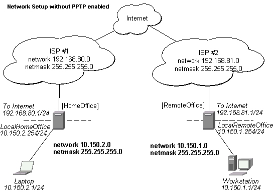
There are two routers in this example:
-
[HomeOffice]
Interface LocalHomeOffice 10.150.2.254/24
Interface ToInternet 192.168.80.1/24
-
[RemoteOffice]
Interface ToInternet 192.168.81.1/24
Interface LocalRemoteOffice 10.150.1.254/24
Each router is connected to a different ISP. One router can access another router through the Internet.
On the Preforma PPTP server a user must be set up for the client:
[admin@HomeOffice] ppp secret> add name=ex service=pptp password=lkjrht
local-address=10.0.103.1 remote-address=10.0.103.2
[admin@HomeOffice] ppp secret> print detail
Flags: X - disabled
  0   name="ex" service=pptp caller-id="" password="lkjrht" profile=default
      local-address=10.0.103.1 remote-address=10.0.103.2 routes==""

[admin@HomeOffice] ppp secret>
Then the user should be added in the PPTP server list:
[admin@HomeOffice] interface pptp-server> add user=ex
[admin@HomeOffice] interface pptp-server> print
Flags: X - disabled, D - dynamic, R - running
  #     NAME                 USER         MTU   CLIENT-ADDRESS  UPTIME   ENC...
  0     pptp-in1             ex
[admin@HomeOffice] interface pptp-server>
And finally, the server must be enabled:
[admin@HomeOffice] interface pptp-server server> set enabled=yes
[admin@HomeOffice] interface pptp-server server> print
            enabled: yes
                mtu: 1460
                mru: 1460
     authentication: mschap2
    default-profile: default
[admin@HomeOffice] interface pptp-server server>
Add a PPTP client to the RemoteOffice router:
[admin@RemoteOffice] interface pptp-client> add connect-to=192.168.80.1 user=ex \
\... password=lkjrht disabled=no
[admin@RemoteOffice] interface pptp-client> print
Flags: X - disabled, R - running
  0  R name="pptp-out1" mtu=1460 mru=1460 connect-to=192.168.80.1 user="ex"
       password="lkjrht" profile=default add-default-route=no


[admin@RemoteOffice] interface pptp-client>
Thus, a PPTP tunnel is created between the routers. This tunnel is like an Ethernet point-to-point connection between the routers with IP addresses 10.0.103.1 and 10.0.103.2 at each router. It enables 'direct' communication between the routers over third party networks.
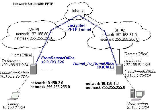
To route the local Intranets over the PPTP tunnel you need to add these routes:
[admin@HomeOffice] > ip route add dst-address 10.150.1.0/24 gateway 10.0.103.2
[admin@RemoteOffice] > ip route add dst-address 10.150.2.0/24 gateway 10.0.103.1
On the PPTP server it can alternatively be done using routes parameter of the user configuration:
[admin@HomeOffice] ppp secret> print detail
Flags: X - disabled
  0   name="ex" service=pptp caller-id="" password="lkjrht" profile=default
      local-address=10.0.103.1 remote-address=10.0.103.2 routes==""

[admin@HomeOffice] ppp secret> set 0 routes="10.150.1.0/24 10.0.103.2 1"
[admin@HomeOffice] ppp secret> print detail
Flags: X - disabled
  0   name="ex" service=pptp caller-id="" password="lkjrht" profile=default
      local-address=10.0.103.1 remote-address=10.0.103.2
      routes="10.150.1.0/24 10.0.103.2 1"

[admin@HomeOffice] ppp secret>
Test the PPTP tunnel connection:
[admin@RemoteOffice]> /ping 10.0.103.1
10.0.103.1 pong: ttl=255 time=3 ms
10.0.103.1 pong: ttl=255 time=3 ms
10.0.103.1 pong: ttl=255 time=3 ms
ping interrupted
3 packets transmitted, 3 packets received, 0% packet loss
round-trip min/avg/max = 3/3.0/3 ms
Test the connection through the PPTP tunnel to the LocalHomeOffice interface:
[admin@RemoteOffice]> /ping 10.150.2.254
10.150.2.254 pong: ttl=255 time=3 ms
10.150.2.254 pong: ttl=255 time=3 ms
10.150.2.254 pong: ttl=255 time=3 ms
ping interrupted
3 packets transmitted, 3 packets received, 0% packet loss
round-trip min/avg/max = 3/3.0/3 ms
To bridge a LAN over this secure tunnel, please see the example in the 'EoIP' section of the manual. To set the maximum speed for traffic over this tunnel, please consult the 'Queues' section.
Connecting a Remote Client via PPTP Tunnel
The following example shows how to connect a computer to a remote office network over PPTP encrypted tunnel giving that computer an IP address from the same network as the remote office has (without need of bridging over EoIP tunnels)
Please, consult the respective manual on how to set up a PPTP client with the software You are using.
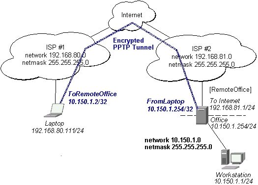
The router in this example:
-
[RemoteOffice]
Interface ToInternet 192.168.81.1/24
Interface Office 10.150.1.254/24
The client computer can access the router through the Internet.
On the PPTP server a user must be set up for the client:
[admin@RemoteOffice] ppp secret> add name=ex service=pptp password=lkjrht
local-address=10.150.1.254 remote-address=10.150.1.2
[admin@RemoteOffice] ppp secret> print detail
Flags: X - disabled
  0   name="ex" service=pptp caller-id="" password="lkjrht" profile=default
      local-address=10.150.1.254 remote-address=10.150.1.2 routes==""

[admin@RemoteOffice] ppp secret>
Then the user should be added in the PPTP server list:
[admin@RemoteOffice] interface pptp-server> add name=FromLaptop user=ex
[admin@RemoteOffice] interface pptp-server> print
Flags: X - disabled, D - dynamic, R - running
  #     NAME                 USER         MTU   CLIENT-ADDRESS  UPTIME   ENC...
  0     FromLaptop           ex
[admin@RemoteOffice] interface pptp-server>
And the server must be enabled:
[admin@RemoteOffice] interface pptp-server server> set enabled=yes
[admin@RemoteOffice] interface pptp-server server> print
            enabled: yes
                mtu: 1460
                mru: 1460
     authentication: mschap2
    default-profile: default
[admin@RemoteOffice] interface pptp-server server>
Finally, the proxy APR must be enabled on the 'Office' interface:
[admin@RemoteOffice] interface ethernet> set Office arp=proxy-arp
[admin@RemoteOffice] interface ethernet> print
Flags: X - disabled, R - running
  #    NAME                 MTU   MAC-ADDRESS       ARP
  0  R ToInternet           1500  00:30:4F:0B:7B:C1 enabled
  1  R Office               1500  00:30:4F:06:62:12 proxy-arp
[admin@RemoteOffice] interface ethernet>
PPTP Setup for Windows
Microsoft provides PPTP client support for Windows NT, 2000, ME, 98SE, and 98. Windows 98SE, 2000, and ME include support in the Windows setup or automatically install PPTP. For 95, NT, and 98, installation requires a download from Microsoft. Many ISPs have made help pages to assist clients with Windows PPTP installation.
Sample instructions for PPTP (VPN) installation and client setup - Windows 98SE
If the VPN (PPTP) support is installed, select 'Dial-up Networking' and 'Create a new connection'. The option to create a 'VPN' should be selected. If there is no 'VPN' options, then follow the installation instructions below. When asked for the 'Host name or IP address of the VPN server', type the IP address of the router. Double-click on the 'new' icon and type the correct user name and password (must also be in the user database on the router or RADIUS server used for authentication).
The setup of the connections takes nine seconds after selection the 'connect' button. It is suggested that the connection properties be edited so that 'NetBEUI', 'IPX/SPX compatible', and 'Log on to network' are unselected. The setup time for the connection will then be two seconds after the 'connect' button is selected.
To install the 'Virtual Private Networking' support for Windows 98SE, go to the 'Setting' menu from the main 'Start' menu. Select 'Control Panel', select 'Add/Remove Program', select the 'Windows setup' tab, select the 'Communications' software for installation and 'Details'. Go to the bottom of the list of software and select 'Virtual Private Networking' to be installed.
Troubleshooting
Description
-
I use firewall and I cannot establish PPTP connection
Make sure the TCP connections to port 1723 can pass through both directions between your sites. Also, IP protocol 47 should be passed through