
FarSync X.21 Interface
| Document revision: | 1.1 (Fri Mar 05 08:14:24 GMT 2004) |
| Applies to: | V2.9 |
General Information
Summary
The MikroTik RouterOS supports FarSync T-Series X.21 synchronous adapter hardware. These cards provide versatile high performance connectivity to the Internet or to corporate networks over leased lines.
Specifications
Packages required: synchronousLicense required: Level4
Submenu level: /interface farsync
Standards and Technologies: X.21, Frame Relay, PPP
Hardware usage: Not significant
Related Documents
Additional Resources
Synchronous Interface Configuration
Submenu level: /interface farsyncDescription
You can change the interface name to a more descriptive one using the set command. To enable the interface, use the enable command.
Property Description
hdlc-keepalive (time; default: 10s) - Cisco HDLC keepalive period in seconds clock-rate (integer; default: 64000) - the speed of internal clock clock-source (external | internal; default: external) - clock source disabled (yes | no; default: yes) - shows whether the interface is disabled frame-relay-dce (yes | no; default: no) - operate in Data Communications Equipment mode frame-relay-lmi-type (ansi | ccitt; default: ansi) - Frame Relay Local Management Interface type line-protocol (cisco-hdlc | frame-relay | sync-ppp; default: sync-ppp) - line protocol media-type (V24 | V35 | X21; default: V35) - type of the media mtu (integer; default: 1500) - Maximum Transmit Unit name (name; default: farsyncN) - assigned interface nameExample
[admin@MikroTik] > interface print
Flags: X - disabled, D - dynamic, R - running
  #    NAME                 TYPE             MTU
  0  R ether1               ether            1500
  1 X  farsync1             farsync          1500
  2 X  farsync2             farsync          1500
[admin@MikroTik] interface>
[admin@MikroTik] interface> enable 1
[admin@MikroTik] interface> enable farsync2
[admin@MikroTik] > interface print
Flags: X - disabled, D - dynamic, R - running
  #    NAME                 TYPE             MTU
  0  R ether1               ether            1500
  1    farsync1             farsync          1500
  2    farsync2             farsync          1500
[admin@MikroTik] interface>farsync
[admin@MikroTik] interface farsync> print
Flags: X - disabled, R - running
  0    name="farsync1" mtu=1500 line-protocol=sync-ppp media-type=V35
       clock-rate=64000 clock-source=external chdlc-keepalive=10s
       frame-relay-lmi-type=ansi frame-relay-dce=no

  1    name="farsync2" mtu=1500 line-protocol=sync-ppp media-type=V35
       clock-rate=64000 clock-source=external chdlc-keepalive=10s
       frame-relay-lmi-type=ansi frame-relay-dce=no

[admin@MikroTik] interface farsync>
You can monitor the status of the synchronous interface:
[admin@MikroTik] interface farsync> monitor 0
           card-type: T2P FarSync T-Series
               state: running
         firmware-id: 2
    firmware-version: 0.7.0
      physical-media: V35
               cable: detected
               clock: not-detected
       input-signals: CTS
      output-signals: RTS DTR

[admin@MikroTik] interface farsync>
Troubleshooting
Description
-
The farsync interface does not show up under the interface list
Obtain the required license for synchronous feature
-
The synchronous link does not work
Check the cabling and the line between the modems. Read the modem manual
Synchronous Link Applications
MikroTik router to MikroTik router
Let us consider the following network setup with two MikroTik routers connected to a leased line with baseband modems:

The interface should be enabled according to the instructions given above. The IP addresses assigned to the synchronous interface should be as follows:
[admin@MikroTik] ip address> add address 1.1.1.1/32 interface farsync1 \
\... network 1.1.1.2 broadcast 255.255.255.255
[admin@MikroTik] ip address> print
Flags: X - disabled, I - invalid, D - dynamic
  #   ADDRESS            NETWORK         BROADCAST       INTERFACE
  0   10.0.0.254/24      10.0.0.254      10.0.0.255      ether2
  1   192.168.0.254/24   192.168.0.254   192.168.0.255   ether1
  2   1.1.1.1/32         1.1.1.2         255.255.255.255 farsync1
[admin@MikroTik] ip address> /ping 1.1.1.2
1.1.1.2 64 byte pong: ttl=255 time=31 ms
1.1.1.2 64 byte pong: ttl=255 time=26 ms
1.1.1.2 64 byte pong: ttl=255 time=26 ms
3 packets transmitted, 3 packets received, 0% packet loss
round-trip min/avg/max = 26/27.6/31 ms
[admin@MikroTik] ip address>
Note that for the point-to-point link the network mask is set to 32 bits, the argument network is set to the IP address of the other end, and the broadcast address is set to 255.255.255.255. The default route should be set to the gateway router 1.1.1.2:
[admin@MikroTik] ip route> add gateway 1.1.1.2
[admin@MikroTik] ip route> print
Flags: X - disabled, I - invalid, D - dynamic, J - rejected,
C - connect, S - static, R - rip, O - ospf, B - bgp
    #    DST-ADDRESS        G GATEWAY         DISTANCE INTERFACE
    0  S 0.0.0.0/0          r 1.1.1.2         1        farsync1
    1 DC 10.0.0.0/24        r 10.0.0.254      1        ether2
    2 DC 192.168.0.0/24     r 192.168.0.254   0        ether1
    3 DC 1.1.1.2/32         r 0.0.0.0         0        farsync1

[admin@MikroTik] ip route>
The configuration of the MikroTik router at the other end is similar:
[admin@MikroTik] ip address> add address 1.1.1.2/32 interface fsync \
\... network 1.1.1.1 broadcast 255.255.255.255
[admin@MikroTik] ip address> print
Flags: X - disabled, I - invalid, D - dynamic
  #   ADDRESS            NETWORK         BROADCAST       INTERFACE
  0   10.1.1.12/24       10.1.1.12       10.1.1.255      Public
  1   1.1.1.2/32         1.1.1.1         255.255.255.255 fsync
[admin@MikroTik] ip address> /ping 1.1.1.1
1.1.1.1 64 byte pong: ttl=255 time=31 ms
1.1.1.1 64 byte pong: ttl=255 time=26 ms
1.1.1.1 64 byte pong: ttl=255 time=26 ms
3 packets transmitted, 3 packets received, 0% packet loss
round-trip min/avg/max = 26/27.6/31 ms
[admin@MikroTik] ip address>
MikroTik router to MikroTik router P2P using X.21 line
Consider the following example:
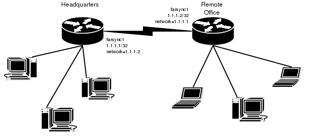
The default value of the property clock-source must be changed to internal for one of the cards. Both cards must have media-type property set to X21.
IP address configuration on both routers is as follows (by convention, the routers are named hq and office respectively):
[admin@hq] ip address> pri
Flags: X - disabled, I - invalid, D - dynamic
  #   ADDRESS            NETWORK         BROADCAST       INTERFACE
  0   192.168.0.1/24     192.168.0.0     192.168.0.255   ether1
  1   1.1.1.1/32         1.1.1.2         1.1.1.2         farsync1

[admin@hq] ip address>

[admin@office] ip address>
Flags: X - disabled, I - invalid, D - dynamic
  #   ADDRESS            NETWORK         BROADCAST       INTERFACE
  0   10.0.0.112/24      10.0.0.0        10.0.0.255      ether1
  1   1.1.1.2/32         1.1.1.1         1.1.1.1         farsync1

[admin@office] ip address>
MikroTik router to Cisco router using X.21 line
Assume we have the following configuration:
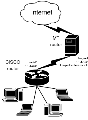
The configuration of MT router is as follows:
[admin@MikroTik] interface farsync> set farsync1 line-protocol=cisco-hdlc \
\... media-type=X21 clock-source=internal
[admin@MikroTik] interface farsync> enable farsync1
[admin@MikroTik] interface farsync> print
Flags: X - disabled, R - running
  0  R name="farsync1" mtu=1500 line-protocol=cisco-hdlc media-type=X21
       clock-rate=64000 clock-source=internal chdlc-keepalive=10s
       frame-relay-lmi-type=ansi frame-relay-dce=no

  1 X  name="farsync2" mtu=1500 line-protocol=sync-ppp media-type=V35
       clock-rate=64000 clock-source=external chdlc-keepalive=10s
       frame-relay-lmi-type=ansi frame-relay-dce=no

[admin@MikroTik] interface farsync>
[admin@MikroTik] interface farsync> /ip address add address=1.1.1.1/24 \
\... interface=farsync1
The essential part of the configuration of Cisco router is provided below:
interface Serial0
 ip address 1.1.1.2 255.255.255.0
 no ip route-cache
 no ip mroute-cache
 no fair-queue
!
ip classless
ip route 0.0.0.0 0.0.0.0 1.1.1.1
MikroTik router to MikroTik router using Frame Relay
Consider the following example:
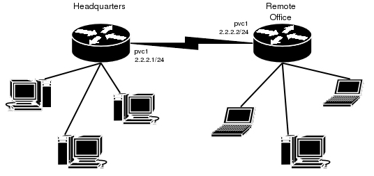
The default value of the property clock-source must be changed to internal for one of the cards. This card also requires the property frame-relay-dce set to yes. Both cards must have media-type property set to X21 and the line-protocol set to frame-relay.
Now we need to add pvc interfaces:
[admin@hq] interface pvc> add dlci=42 interface=farsync1
[admin@hq] interface pvc> print
Flags: X - disabled, R - running
  #    NAME                                                 MTU  DLCI INTERFACE
  0 X  pvc1                                                 1500 42   farsync1

[admin@hq] interface pvc>
Similar routine has to be done also on office router:
[admin@office] interface pvc> add dlci=42 interface=farsync1
[admin@office] interface pvc> print
Flags: X - disabled, R - running
  #    NAME                                                 MTU  DLCI INTERFACE
  0 X  pvc1                                                 1500 42   farsync1

[admin@office] interface pvc>
Finally we need to add IP addresses to pvc interfaces and enable them.
On the hq router:
[admin@hq] interface pvc> /ip addr add address 2.2.2.1/24 interface pvc1
[admin@hq] interface pvc> /ip addr print
Flags: X - disabled, I - invalid, D - dynamic
  #   ADDRESS            NETWORK         BROADCAST       INTERFACE
  0   10.0.0.112/24      10.0.0.0        10.0.0.255      ether1
  1   192.168.0.1/24     192.168.0.0     192.168.0.255   ether2
  2   2.2.2.1/24         2.2.2.0         2.2.2.255       pvc1

[admin@hq] interface pvc> enable 0
[admin@hq] interface pvc>
and on the office router:
[admin@office] interface pvc> /ip addr add address 2.2.2.2/24 interface pvc1
[admin@office] interface pvc> /ip addr print
Flags: X - disabled, I - invalid, D - dynamic
  #   ADDRESS            NETWORK         BROADCAST       INTERFACE
  0   10.0.0.112/24      10.0.0.0        10.0.0.255      ether1
  1   2.2.2.2/24         2.2.2.0         2.2.2.255       pvc1

[admin@office] interface pvc> enable 0
[admin@office] interface pvc>
Now we can monitor the synchronous link status:
[admin@hq] interface pvc> /ping 2.2.2.2
2.2.2.2 64 byte ping: ttl=64 time=20 ms
2.2.2.2 64 byte ping: ttl=64 time=20 ms
2.2.2.2 64 byte ping: ttl=64 time=21 ms
2.2.2.2 64 byte ping: ttl=64 time=21 ms
4 packets transmitted, 4 packets received, 0% packet loss
round-trip min/avg/max = 20/20.5/21 ms
[admin@hq] interface pvc> /interface farsync monitor 0
           card-type: T2P FarSync T-Series
               state: running-normally
         firmware-id: 2
    firmware-version: 1.0.1
            physical: X.21
               cable: detected
               clock: detected
       input-signals: CTS
      output-signals: RTS,DTR

[admin@hq] interface pvc>