IP Telephony
Document revision 1.5 (11-Aug-2003)This document applies to the MikroTik RouterOS V2.7
Table Of Contents
- Table Of Contents
- Summary
- Specifications
- Related Documents
- Description
- IP Telephony Specifications
- IP Telephony Hardware Installation
- IP Telephony Configuration
- Description
- Monitoring the Voice Ports
- Voice-Port Statistics
- Voice Port for Telephony cards
- Voice Port for Voicetronix cards
- Voice Port for ISDN
- Voice Port for Voice over IP (voip)
- Numbers
- Regional Settings
- Audio CODEC
- AAA
- IP Telephony Gatekeeper
- IP Telephony Troubleshooting
- IP Telephony Applications
- Setting up the MikroTik IP Telephone
- Setting up the IP Telephony Gateway
- Setting up the Welltech IP Telephone
- Setting up the MikroTik Router and CISCO Router
- Setting up PBX to PBX Connection over an IP Network
- Additional Resources
Summary
The MikroTik RouterOS IP Telephony feature enables Voice over IP (VoIP) communications using routers equipped with the following voice port hardware:
- Quicknet LineJACK or PhoneJACK analog telephony cards
- ISDN cards
- Voicetronix OpenLine4 (was V4PCI) - 4 analog telephone lines cards
- Zaptel Wildcard X100P IP telephony card - 1 analog telephone line
Specifications
Packages required : telephonyLicense required : Any
Home menu level : /ip telephony
Protocols utilized : Complete list of VoIP protocols
Hardware usage: may require additional RAM (64MB recommended)
Related Documents
Software Package Installation and UpgradingISDN Interface
Authentication, Authorization and Accounting
Description
IP telephony, known as Voice over IP (VoIP), is the transmission of telephone calls over a data network like one of the many networks that make up the Internet. There are four ways that you might talk to someone using VoIP:- Computer-to-computer - This is certainly the easiest way to use VoIP, and you don't have to pay for long-distance calls.
- Computer-to-telephone - This method allows you to call anyone (who has a phone) from your computer. Like computer-to-computer calling, it requires a software client. The software is typically free, but the calls may have a small per-minute charge.
- Telephone-to-computer - Allows a standard telephone user to initiate a call to a computer user.
- Telephone-to-telephone - Through the use of gateways, you can connect directly with any other standard telephone in the world.
IP Telephony Specifications
Supported Hardware
The MikroTik RouterOS V2.7 supports following telephony cards from Quicknet Technologies, Inc. (www.quicknet.net):- Internet PhoneJACK (ISA) for connecting an analog telephone,
- Internet LineJACK (ISA) for connecting an analog telephone line or a telephone.
The MikroTik RouterOS V2.7 supports the Voicetronix OpenLine4 card for connecting four (4) analog telephone lines telephony cards from Voicetronix, Inc. (www.voicetronix.com.au)
The MikroTik RouterOS V2.7 supports the Zaptel Wildcard X100P IP telephony card for connecting one analog telephone line from Linux Support Services (www.digium.com)
Supported Standards
- Standards for VoIP
The MikroTik RouterOS supports IP Telephony in compliance with the International Telecommunications Union - Telecommunications (ITU-T) specification H.323v4. H.323 is a specification for transmitting multimedia (voice, video, and data) across an IP network. H.323v4 includes: H.245, H.225, Q.931, H.450.1, RTP(real-time protocol) - CODECs
The following audio CODECs are supported:
G.711 - the 64 kbps Pulse code modulation (PCM) voice coding technique. The encoded voice is already in the correct format for digital voice delivery in the PSTN or through PBXs.
G.723.1 - the 6.3 kbps compression technique that can be used for compressing audio signal at very low bit rate.
GSM-06.10 - the 13.2 kbps coding
LPC-10 - the 2.5 kbps coding
G.729, G.729a - the 8 kbps CS-ACELP software coding
G.728 - 16 kbps coding technique, supported only on Quicknet LineJACK cards - RFCs
Compliant to the RFC1889(RTP) http://www.ietf.org/rfc/rfc1889.txt?number=1889 - Regional Standards
Quicknet cards are approved in United States, United Kingdom, France, Germany, Australia, Japan.
Voicetronix OpenLine4 is approved in Australia, Europe, New Zealand and USA (FCC).
Implementation Options
- IP Telephony Gateway
When connected to a PBX or PSTN telephone line, the MikroTik router can act as a gateway between the telephone network and the VoIP network. - IP Telephone System
When connecting an analog telephone, the MikroTik router acts as an IP Telephone
- Microsoft Netmeeting
- Siemens IP phone HiNet LP 5100
- Cisco ATA 186
- Welltech LAN Phone 101
- Most H.323 compatible devices
IP Telephony Hardware Installation
Please install the telephony hardware into the PC accordingly the instructions provided by card manufacturer. Each installed Quicknet card requires IO memory range in the following sequence: the first card occupies addresses 0x300-0x31f, the second card 0x320-0x33f, the third 0x340-0x35f, and so on. Make sure there is no conflict in these ranges with other devices, e.g., network interface cards, etc.
If the MikroTik router will be used as
- an IP telephone - connect an analog telephone with tone dialing capability to the PhoneJACK or LineJACK card,
- an IP telephony gateway - connect an analog telephone line to the LineJACK, Voicetronix, Zaptel card or ISDN telephone line to ISDN card.
Please consult the ISDN Manual for more information about installing the ISDN adapters.
IP Telephony Configuration
Submenu level : /ip telephonyDescription
The IP Telephony requires IP network connection and configuration. The basic IP configuration can be done under the /ip address and /ip route menus.Telephony Voice Ports
Submenu level : /ip telephony voice-portDescription
This submenu is used for managing all IP telephony voice ports (linejack, phonejack, isdn, voip, voicetronix, zaptel).Property Description
name - assigned name of the voice porttype (read-only: unknown | phonejack | linejack | phonejack-lite | phonejack-pci | voip | isdn | voicetronix | zaptel) - type of the installed telephony voice port:
autodial (integer; default: "") - number to be dialed automatically, if call is coming in from this voice port
Notes
If autodial does not exactly match an item in /ip telephony numbers, there can be two possibilities:Monitoring the Voice Ports
Property Description
status (read-only: on-hook | off-hook | ring | connection | busy) - current state of the port:- on-hook - the handset is on-hook, no activity
- off-hook - the handset is off-hook, the number is being dialed
- ring - call in progress, direction of the call is shown by the argument direction
- connection - the connection has been established
- busy - the connection has been terminated, the handset is still off-hook
- phone - telephone connected to the card (POTS)
- line - line connected to the linejack card (PSTN)
- ip-to-port - call from the IP network to the voice card
- port-to-ip - call from the voice card to an IP address
- plugged - the telephone line is connected to the PSTN port of the card
- unplugged - there is no working line connected to the PSTN port of the card
remote-party-name (name, integer) - name and IP address of the remote party
codec (name) - CODEC used for the audio connection
duration (time) - duration of the audio call
Notes
Monitoring feature is not available for VoIP ports.Use the monitor command under the corresponding menu to view the current state of the port.
Example
The following example will monitor linejack voice port:
[admin@MikroTik] ip telephony voice-port linejack> monitor PBX_Line
               status: connection
                 port: phone
            direction: port-to-ip
          line-status: unplugged
         phone-number: 26
    remote-party-name: pbx_20 [10.5.8.12]
                codec: G.723.1-6.3k/hw
             duration: 14s

[admin@MikroTik] ip telephony voice-port linejack>
Voice-Port Statistics
Notes
Voice-port statistics are available for all local voice ports (only VoIP voice ports do not provide this ability).Use the show-stats command under the corresponding menu to view the statistics of current audio connection.
Example
The following example will shows statistics of LineJACK card:
[admin@MikroTik] ip telephony voice-port linejack> show-stats PBX_Line
        round-trip-delay: 5ms
            packets-sent: 617
              bytes-sent: 148080
               send-time: 31ms/30ms/29ms
        packets-received: 589
          bytes-received: 141360
            receive-time: 41ms/30ms/19ms
    average-jitter-delay: 59ms
            packets-lost: 0
    packets-out-of-order: 0
        packets-too-late: 2

[admin@MikroTik] ip telephony voice-port linejack>
The average-jitter-delay shows the approximate delay time till the received voice packet
is forwarded to the driver for playback. The value shown is never less than 30ms, although the
actual delay time could be less. If the shown value is >40ms, then it is close (+/-1ms) to the
real delay time.
The jitter buffer preserves quality of the voice signal against the loss or delay of packets while traveling over the network. The larger the jitter buffer, the larger the total delay, but fewer packets lost due to timeout. If the jitter-buffer=0, then it is adjusted automatically during the conversation to keep lost packet rate under 1%. The average-jitter-delay is the approximate average time from the moment of receiving an audio packet from the IP network till it is played back over the telephony voice port.
The total delay from the moment of recording the voice signal till its playback is
the sum of following three delay times:
- delay time at the recording point (approx. 38ms),
- delay time of the IP network (1..5ms and up),
- delay time at the playback point (the jitter delay).
A voice call can be terminated using the clear-call command (not available for VoIP voice ports). If the voiceport has an active connection, the command clear-call voiceport terminates it. The command is useful in cases, when the termination of connection has not been detected by one of the parties, and there is an "infinite call". It can also be used to terminate someone's call, if it is using up the line required for another call.
Voice Port for Telephony cards
Property Description
name - name given by the user or the default onetype (read-only: phonejack | phonejack-lite | phonejack-pci) - (only for PhoneJACK) type of the card, cannot be changed
autodial (integer; default: "") - phone number which will be dialed immediately after the handset has been lifted. If this number is incomplete, then the remaining part has to be dialed on the dial-pad. If the number is incorrect, busy tone is played. If the number is correct, then the appropriate number is dialed. If it is an incoming call from the PSTN line (linejack), then the directcall mode is used - the line is picked up only after the remote party answers the call.
playback-volume (integer; default: 0) - playback volume in dB, 0dB means no change, possible values are -48...48dB
record-volume (integer; default: 0) - record volume in dB, 0dB means no change, possible values are -48...48dB.
ring-cadence (string) - (only for quicknet cards) a 16-symbol ring cadence for the phone, each symbol is 0.5 seconds, + means ringing, - means no ringing.
region (australia | estonia | france | germany | japan | latvia | lithuania | mikrotik | uk | us; default: us) - regional setting for the voice port. For phonejack, this setting is used for generating the tones. For linejacks, this setting is used for setting the parameters of PSTN line, as well as for detecting and generating the tones.
aec (yes | no; default: yes) - echo detection and cancellation.
If the echo cancellation is on, then the following parameters are used:
agc-on-playback (yes | no; default: no) - automatic gain control on playback (can not be used together with hardware voice codecs)
agc-on record (yes | no; default: no) - automatic gain control on record (can not be used together with hardware voice codecs)
detect-cpt (yes | no; default: no) - automatically detect call progress tones
Notes
All commands relating the Quicknet, Voicetronix and Zaptel Wildcard cards are listed under the /ip telephony voice-port submenus:
[admin@MikroTik] ip telephony voice-port linejack> print
Flags: X - disabled
  0   name="linejack1" autodial="" region=us playback-volume=0
      record-volume=0 ring-cadence="++-++--- ++-++---" agc-on-playback=no
      agc-on-record=no aec=yes aec-tail-length=short aec-nlp-threshold=low
      aec-attenuation-scaling=4 aec-attenuation-boost=0 software-aec=no
      detect-cpt=yes


[admin@MikroTik] ip telephony voice-port linejack>
For linejacks, there is a command blink voiceport,
which blinks the LEDs of the specified voiceport for five seconds after it is invoked.
This command can be used to locate the respective card from several linejack cards.
Voice Port for Voicetronix cards
Submenu level : /ip telephony voice-port voicetronixProperty Description
Voicetronix telephony cards have some additional properties other cards haven't:
balance-registers (integer; default: 199) - registers which
depend on telephone line impedance. Can be adjusted to get best echo cancellation
balance-status (read-only: integer) - shows quality of
hardware echo cancellation in dB
loop-drop-detection (yes | no; default: yes) - automatically clear
call when loop drop is detected
Notes
balance-status depends on balance-registers value. When balance-registers are changed, gets status unknown. After test-balance command execution gets some value in dB - the less, the better. At least -6dB or less is required for echo canceller to do his job.As some Voicetronix cards fail to detect loop drop correctly, with loop-drop-detection you can manage whether loop drop detection feature is enabled.
Voicetronix telephony cards also have some additional commands that other cards haven't:
Some tips for testing balance registers:
- test is sensitive to noise from the phone, so it's recommended to cover mouth peice during it;
- find-best-balance can be interrupted by clean-call command;
- once best balance-registers value is known, it can be set manually to this best value for all voicetronix voice ports, which will use the same telephone line;
- balance-registers should be changed only if echo cancellation on voicetronix card does not work good enough. Echo cancellation problems can imply DTMF and busy-tone detection failures.
- balance-registers value has to be in format bal1[,bal3[,bal2]], where bal1, bal2, bal3 - balance registers. bal1 has to be in interval 192..248 (0xC0..0xF8). The others should be in interval 0..255 (0x00..0xFF).
Voice Port for ISDN
Submenu level : /ip telephony voice-port isdnProperty Description
name - Name given by the user or the default one.msn (integer) - Telephone number of the ISDN voice port (ISDN MSN number).
lmsn (character) - msn pattern to listen on. It determines which calls from the ISDN line this voice port should answer. If left empty, msn is used. Meaning of special symbols:
- ; - separates pattern entries (more than one pattern can be specified this way)
- ? - matches one character
- * - matches zero or more characters
- [ ] - matches any single character from the set in brackets
- [^ ] - matches any single character not from the set in brackets
playback-volume (integer; default: 0) - playback volume in dB, 0dB means no change, possible values are -48...48dB.
record-volume (integer; default: 0) - record volume in dB, 0dB means no change, possible values are -48...48dB.
region (australia | estonia | france | germany | japan | latvia | lithuania | mikrotik | uk | us; default: us) - regional setting for the voice port (for tone generation only).
aec (yes | no; default: yes) - echo detection and cancellation. Possible values are yes and no. If the echo cancellation is on, then aec-tail-length parameter is used.
aec-tail-length (short | medium | long; default: short) - size of the buffer of echo detection. Possible values are: short (8 ms), medium (16 ms), long (32 ms).
software-aec (yes | no; default: no) - software echo cancellation (experimental)
agc-on-playback (yes | no; default: no) - automatic gain control on playback
agc-on-record (yes | no; default: no) - automatic gain control on record
Notes
In contrary to the phonejack and linejack voice ports, which are as many as the number of cards installed, the isdn ports can be added as many as desired.Example
[admin@MikroTik] ip telephony voice-port isdn> print
Flags: X - disabled
  0   name="isdn1" autodial="" region=germany msn="140" lmsn=""
      playback-volume=0 record-volume=0 agc-on-playback=no agc-on-record=no
      software-aec=no aec=yes aec-tail-length=short

[admin@MikroTik] ip telephony voice-port isdn>
Voice Port for Voice over IP (voip)
Submenu level : /ip telephony voice-port voipDescription
The voip voice ports are virtual ports, which designate a voip channel to another host over the IP network. You must have at least one voip voice port to be able to make calls to other H.323 devices over IP network.Property Description
name - Name given by the user or the default one.
remote-address (IP address; default: 0.0.0.0) - IP address of the remote party (IP telephone or gateway) associated with this voice port.
If the call has to be performed through this voice port, then the specified IP address is called.
If there is an incoming call from the specified IP address, then the parameters of this voice port are used.
If there is an incoming call from an IP address, which is not specified in any of the voip voice port records,
then the default record is used.
If there is no default record, then default values are used.
autodial (integer) - phone number which will be added in front of the telephone number received over the IP network.
In most cases it should be blank.
jitter-buffer (integer; default: 100ms ) - size of the jitter buffer, 0...1000ms.
The jitter buffer preserves quality of the voice signal against the loss or delay of packets
while traveling over the network.
The larger the jitter buffer, the larger the total delay, but fewer packets lost due to timeout.
If the setting is jitter-buffer=0, the size of it is adjusted automatically during the conversation,
to keep amount of lost packets under 1%.
silence-detection (yes | no; default: no) - if yes, then silence is detected and no audio data
is sent over the IP network during the silence period.
prefered-codec (none | G.711-ALaw-64k/hw | G.711-ALaw-64k/sw | G.711-uLaw-64k/hw | G.711-uLaw-64k/sw |
G.723.1-6.3k/hw | G.723.1-6.3k/sw | G.729-8k/sw | G.729A-8k/sw | GSM-06.10-13.2k/sw | LPC-10-2.5k/sw; default: none) - the preferred codec to be used for this voip voice port.
If possible, the specified codec will be used.
fast-start (yes | no; default: yes) - allow or disallow the fast start. The fast start allows establishing
the audio connection in a shorter time. However, not all H.323 endpoints support this feature.
Therefore, it should be turned off, if there are problems to establish telephony connection using the fast start mode.
Example
[admin@MikroTik] ip telephony voice-port voip> print detail
Flags: X - disabled, D - dynamic, R - registered
  0    name="test" autodial="" remote-address=0.0.0.0 jitter-buffer=100ms
       prefered-codec=none silence-detection=no fast-start=yes


[admin@MikroTik] ip telephony voice-port voip>
Numbers
Submenu level : /ip telephony numbersDescription
This is the so-called "routing table" for voice calls. This table assigns numbers to the voice ports.The main function of the numbers routing table is to determine:- to which voice port route the call, and
- what number to send over to the remote party.
Property Description
dst-pattern (integer) - pattern of the telephone number.
Symbol . designate any digit, symbol _ (only as the last one) designate any symbols (i.e.
any number of characters can follow, ended with # character)
voice-port (name) - voice port to be used when calling the specified telephone number.
prefix (integer) - prefix, which will be used to substitute the known part of the destination-pattern,
i.e., the part containing digits.
The dst-pattern argument is used to determine which voice port to be used,
whereas the prefix argument designates the number to dial over the voice port (be sent over to the remote party).
If the remote party is an IP telephony gateway, then the number will be used for making the call.
Notes
More than one entry can be added with exactly the same dst-pattern. If first one of them is already busy, next one with the same dst-pattern is used. Telephony number entries can be moved, to select desired order.Example
The example of actual printout:[admin@MikroTik] ip telephony numbers> print Flags: I - invalid, X - disabled, D - dynamic, R - registered # DST-PATTERN VOICE-PORT PREFIX 0 26 VoIP_GW 26 [admin@MikroTik] ip telephony numbers>Let us consider the following example for the number table:
[admin@MikroTik] ip telephony numbers> print
Flags: I - invalid, X - disabled, D - dynamic, R - registered
 #     DST-PATTERN                  VOICE-PORT     PREFIX
 0     12345                                XX
 1     1111.                                YY
 2     22...                                ZZ      333
 3     ...                                  QQ      55

[admin@MikroTik] ip telephony numbers>
We will analyze the Number Received (nr) - number dialed at the telephone, or received over the line, the Voice Port (vp) - voice port to be used for the call, and the Number to Call (nc) - number to be called over the Voice Port.
If nr=55555, it does not match any of the destination patterns, therefore it is rejected.
If nr=123456, it does not match any of the destination patterns, therefore it is rejected.
If nr=1234, it does not match any of the destination patterns (incomplete for record #0), therefore it is rejected.
If nr=12345, it matches the record #0, therefore number "" is dialed over the voice port XX.
If nr=11111, it matches the record #1, therefore number "1" is dialed over the voice port YY.
If nr=22987, it matches the record #2, therefore number "333987" is dialed over the voice port ZZ.
If nr=22000, it matches the record #2, therefore number "333000" is dialed over the voice port ZZ.
If nr=444, it matches the record #3, therefore number "55444" is dialed over the voice port QQ.
Let us add a few more records:
[admin@MikroTik] ip telephony numbers> print
Flags: I - invalid, X - disabled, D - dynamic, R - registered
   #     DST-PATTERN                  VOICE-PORT     PREFIX
 .....
   4     222                            KK           44444
   5     3..                            LL           553

[admin@MikroTik] ip telephony numbers>
If nr=222 => the best match is the record # 4=> nc=44444, vp=KK.
The 'best match' means that it has the most coinciding digits
between the nr and destination-pattern.
If nr=221 => incomplete record # 2 => call is rejected
If nr=321 => the best match is the record # 5 => nc=55321, vp=LL
If nr=421 => matches the record # 3 => nc=55421, vp=QQ
If nr=335 => the best match is the record # 5 => nc=55321, vp=LL
Let us add a few more records:
[admin@MikroTik] ip telephony numbers> print
Flags: I - invalid, X - disabled, D - dynamic, R - registered
   #     DST-PATTERN                  VOICE-PORT     PREFIX
 .....
   6     33...                        MM              33
   7     11.                          NN              7711

[admin@MikroTik] ip telephony numbers>
If nr=335 => incomplete record # 6 => the call is rejected.
Explanation of this case:
The nr=335 fits perfectly both the record # 3 and # 5. The # 5 is chosen as the 'best match' candidate at the moment. Furthermore, there is record # 6, which has two matching digits (more than for # 3 or # 5). Therefore the # 6 is chosen as the 'best match'. However, the record # 6 requires five digits, but the nr has only three. Two digits are missing, therefore the number is incomplete. Two additional digits would be needed to be entered on the dialpad. If the number is sent over from the network, it is rejected.If nr=325 => matches the record # 5 => nc=55325, vp=LL
If nr=33123 => matches the record # 6 => nc=33123, vp=MM
If nr=123 => incomplete record # 0 => call is rejected
If nr=111 => incomplete record # 1 => call is rejected
If nr=112 => matches the record # 7 => nc=77112, vp=NN
If nr=121 => matches the record # 3 => nc=55121, vp=QQ
It is impossible to add the following records:
[admin@MikroTik] ip telephony numbers> print
Flags: I - invalid, X - disabled, D - dynamic, R - registered
   #     DST-PATTERN             VOICE-PORT
 .....                                                      reason:
         11                              DD             conflict with record # 1
                                                        and # 7
         11..                            DD             conflict with record # 7
         111                             DD             conflict with record # 1
         22.                             DD             conflict with record # 2
         .....                           DD             conflict with record # 3
Regional Settings
Submenu level : /ip telephony regionDescription
Regional settings are used to adjust the voice port properties to the PSTN system or the PBX. For example, to detect hang-up from line, there has to be correct regional setting for the LineJACK card: there must be correct busy-tone-frequency and busy-tone-cadence set for region which this LineJACK card uses. Without that, detect-cpt parameter for LineJACK's voice port has to be set to true.Property Description
flag - (P) predefined, cannot be changed or removed. Users can add their own regional settings, which can be changed and removed.name - Name of the regional setting
busy-tone-cadence (integer; default: 500,500) - Busy tone cadence in ms (0 - end of cadence), 0...30000
busy-tone-frequency (integer x integer; default: 440x0) - Frequency (20...2000) and volume gain (-24...6) of busy tone Hz x dB.
data-access-arrangement (australia | france | germany | japan | uk | us; default: us) - ring voltage, impedance setting for line-jack card
dial-tone-frequency (integer x integer; default: 440x0) - Frequency (20...2000) and volume gain (-24...6) of dial tone Hz x dB
dtmf-tone-cadence (integer; default: 180,60) - Dual Tone Multi Frequency tone cadence in ms
dtmf-tone-volume (integer; default: -3,-3) - Dual Tone Multi Frequency tone volume in dB ring-tone-cadence (integer; default: 1000,2000) - Ring tone cadence in ms (0 - end of cadence), 0...30000
ring-tone-frequency (integer x integer; default: 440x0) - Frequency (20...2000) and volume gain (-24...6) of ring tone Hz x dB
Notes
For generating the tone, the frequency and cadence arguments are used. The dialtone always is continuous signal, therefore it does not have the cadence argument. When detecting the dialtone, it should be at least 100ms long.Example
[admin@MikroTik] ip telephony region> print
Flags: P - predefined
  0 P name="us" data-access-arrangement=us dial-tone-frequency=350x0,440x0
      busy-tone-frequency=480x0,620x0 busy-tone-cadence=500,500,500,500
      ring-tone-frequency=480x0,440x0 ring-tone-cadence=2000,4000
      dtmf-tone-volume=-3,-3 dtmf-tone-cadence=180,60

  1 P name="uk" data-access-arrangement=uk dial-tone-frequency=350x0,440x0
      busy-tone-frequency=400x0 busy-tone-cadence=375,375,375,375
      ring-tone-frequency=400x0,450x0 ring-tone-cadence=400,200,400,2000
      dtmf-tone-volume=-3,-3 dtmf-tone-cadence=180,60

  2 P name="france" data-access-arrangement=france dial-tone-frequency=440x0
      busy-tone-frequency=440x0 busy-tone-cadence=250,250,250,250
      ring-tone-frequency=440x0 ring-tone-cadence=1500,3500
      dtmf-tone-volume=-3,-3 dtmf-tone-cadence=180,60

  3 P name="germany" data-access-arrangement=germany
      dial-tone-frequency=425x0 busy-tone-frequency=425x0
      busy-tone-cadence=480,480,480,480 ring-tone-frequency=425x0
      ring-tone-cadence=1000,4000 dtmf-tone-volume=-3,-3
      dtmf-tone-cadence=180,60

  ...
Sometimes it is necessary to add an additional regional setting matching the properties
of a particular PBX. The following example will show you how with add command to add a new regional setting:
[admin@MikroTik] ip telephony region> add
Creates new item with specified property values.
        busy-tone-cadence  Busy tone cadence in ms
      busy-tone-frequency  Frequency and volume gain of busy tone Hz x dB
                copy-from  Item number
  data-access-arrangement  Ring voltage, impedance setting for line-jack card
      dial-tone-frequency  Frequency and volume gain of dial tone Hz x dB
        dtmf-tone-cadence  Dual Tone Multi Frequency tone cadence in ms
         dtmf-tone-volume  Dual Tone Multi Frequency tone volume in dB
                     name  Name of the regional setting
        ring-tone-cadence  Ring tone cadence in ms
      ring-tone-frequency  Frequency and volume gain of ring tone Hz x dB
[admin@MikroTik] ip telephony region>
To change, for example, the volume gain of both dial tone frequencies to -6dB
for a user defined region home, you need to enter the command:
[admin@MikroTik] ip telephony region> set home dial-tone-frequency=350x-6,440x-6
Audio CODEC
Submenu level : /ip telephony codecNotes
CODECs are listed according to their priority of use. The highest priority is at the top. CODECs can be enabled, disabled and moved within the list. When connecting with other H.323 systems, the protocol will negotiate the CODEC which both of them support according to the priority order.The hardware codecs (/hw) are built-in CODECs supported by Quicknet cards. If an ISDN card is used, then the hardware CODECs are ignored, only software CODECs (/sw) are used.
The choice of the CODEC type is based on the throughput and speed of the network. Better audio quality can be achieved by using CODEC requiring higher network throughput. The highest audio quality can be achieved by using the G.711-uLaw CODEC requiring 64kb/s throughput for each direction of the call. It is used mostly within a LAN. The G.723.1 CODEC is the most popular one to be used for audio connections over the Internet. It requires only 6.3kb/s throughput for each direction of the call.
Example
[admin@MikroTik] ip telephony codec> print
Flags: X - disabled
  #   NAME
  0   G.723.1-6.3k/sw
  1   G.728-16k/hw
  2   G.711-ALaw-64k/hw
  3   G.711-uLaw-64k/hw
  4   G.711-uLaw-64k/sw
  5   G.711-ALaw-64k/sw
  6   G.729A-8k/sw
  7   GSM-06.10-13.2k/sw
  8   LPC-10-2.5k/sw
  9   G.723.1-6.3k/hw
 10   G.729-8k/sw
[admin@MikroTik] ip telephony codec>
AAA
Submenu level : /ip telephony aaaDescription
AAA (Authentication Authorization Accounting) can be used to configure the RADIUS accounting feature.
[admin@MikroTik] ip telephony aaa> print
    use-radius-accounting: no
           interim-update: 0s
[admin@MikroTik] ip telephony aaa>
Property Description
use-radius-accounting (yes | no; default: no) - defines whether to use radius accounting or not interim-update (integer; default: 0) - defines time interval between communications with the router. If this time will exceed, RADIUS server will assume that this connection is down. This value is suggested to be not less than 3 minutes. If set to 0s, no interim-update messages are sent at all
The contents of the CDR (Call Detail Record) are as follows:
NAS-Identifier - router name (from /system identity print)
NAS-IP-Address - router's local IP address which the connection was
established to (if exist)
NAS-Port-Type - always Async
Event-Timestamp - data and time of the event
Acct-Session-Time - current connection duration (only in INTERIM-UPDATE
and STOP records)
Acct-Output-Packets - sent RTP (Real-Time Transport Protocol) packet
count (only in INTERIM-UPDATE and STOP records)
Acct-Input-Packets - received RTP (Real-Time Transport Protocol) packet
count (only in INTERIM-UPDATE and STOP records)
Acct-Output-Octets - sent byte count (only in INTERIM-UPDATE and STOP records)
Acct-Input-Octets - received byte count (only in INTERIM-UPDATE and STOP records)
Acct-Session-Id - unique session participient ID
h323-disconnect-cause - session disconnect reason (only in STOP records):
- 0 - Local endpoint application cleared call
- 1 - Local endpoint did not accept call
- 2 - Local endpoint declined to answer call
- 3 - Remote endpoint application cleared call
- 4 - Remote endpoint refused call
- 5 - Remote endpoint did not answer in required time
- 6 - Remote endpoint stopped calling
- 7 - Transport error cleared call
- 8 - Transport connection failed to establish call
- 9 - Gatekeeper has cleared call
- 10 - Call failed as could not find user (in GK)
- 11 - Call failed as could not get enough bandwidth
- 12 - Could not find common capabilities
- 13 - Call was forwarded using FACILITY message
- 14 - Call failed a security check and was ended
- 15 - Local endpoint busy
- 16 - Local endpoint congested
- 17 - Remote endpoint busy
- 18 - Remote endpoint congested
- 19 - Could not reach the remote party
- 20 - The remote party is not running an endpoint
- 21 - The remote party host off line
- 22 - The remote failed temporarily app may retry
h323-connect-time - session establish time (only in INTERIM-UPDATE and STOP records)
h323-gw-id - name of gateway emitting message (should be equal to NAS-Identifier)
h323-call-type - call leg type (should be VoIP)
h323-call-origin - indicates origin of call relative to gateway (answer for calls from IP network, originate - to IP network)
h323-setup-time - call setup time
h323-conf-id - unique session ID
h323-remote-address - the remote address of the session
NAS-Port-Id - voice port ID
Acct-Status-Type - record type:
- START - session is established
- STOP - session is closed
- INTERIM-UPDATE (ALIVE) - session is alive. The time between the messages is defined by interim-update-interval parameter (if it is set to 0s, there will be no such messages)
Notes
All the parameters, which names begin with h323, are CISCO vendor specific Radius attributesIP Telephony Gatekeeper
Submenu level : /ip telephony gatekeeper
[admin@MikroTik] ip telephony gatekeeper> print
         gatekeeper: local
          remote-id: ""
     remote-address: 0.0.0.0
         registered: yes
    registered-with: "tst-2.7@localhost"
Property Description
gatekeeper (none | local | remote; default: none) - Gatekeeper name to use- none - don't use any gatekeeper at all
- local - start and use local gatekeeper
- remote - use some other gatekeeper
remote-id (name) - name of remote gatekeeper to use. If left empty, first available gatekeeper will be used. Name of locally started gatekeeper is the same as system identity
Statistics:
registered (yes | no) - shows whether local H.323 endpoint is registered to any gatekeeper
registered-with (name) - name of gatekeeper to which local H.323 endpoint is registered
Notes
For each H.323 endpoint gatekeeper stores its telephone numbers. So, gatekeeper knows all telephone numbers for all registered endpoints. And it knows which telephone number is handled by which endpoint. Mapping between endpoints and their telephone numbers is the main functionality of gatekeepers.If endpoint is registered to endpoint, it does not have to know every single endpoint and every single telephone number, which can be called. Instead, every time some number is dialed, endpoint asks gatekeeper for destination endpoint to call by providing called telephone number to it.
Gatekeeper Configuration
Example
In most simple case with one phonejack card and some remote gatekeeper, configuration can be as follows:
[admin@MikroTik] ip telephony voice-port> print
Flags: X - disabled
  #   NAME                          TYPE            AUTODIAL
  0   phonejack1                phonejack
  1   voip1                         voip

[admin@MikroTik] ip telephony voice-port voip> print
Flags: X - disabled, D - dynamic, R - registered
  #    NAME      AUTODIAL REMOTE-ADDRESS  JITTER-BUFFER PREFERED-CODEC  SIL FAS
  0    voip1              0.0.0.0         0s            none            no  yes

[admin@MikroTik] ip telephony numbers> print
Flags: I - invalid, X - disabled, D - dynamic, R - registered
  #     DST-PATTERN             VOICE-PORT              PREFIX
  0     11                      phonejack1
  1     _                       voip1

[admin@MikroTik] ip telephony gatekeeper> print
         gatekeeper: remote
          remote-id: ""
     remote-address: 10.0.0.98
         registered: yes
    registered-with: "MikroTik@10.0.0.98"
In this case this endpoint will register to gatkeeper at IP address 10.0.0.98
with telephone number 11.
Every call to telephone number 11 will be transfered from gatekeeper to
this endpoint. And this endpoint will route this call to phonejack1 voice port.
On any other telephone number gatekeeper will be asked for real destination.
>From this endpoint it will be possible to call all the endpoints, which are
registered to the same gatekeeper. If that gatekeeper has static entries about
endpoints, which are not registered to gatekeeper, it still will be possible to
call those endpoints by those statically defined telephone numbers at
gatekeeper.
Notes
MikroTik IP telephony package includes very simple gatekeeper. This gatekeeper can be activated by setting "gatekeeper" parameter to "local". In this case local endpoint automatically is registered to local gatekeeper. And any other endpoint can register to this gatekeeper, too.Registered endpoints are added to /ip telephony voice-port voip table. Those entries are marked with "D - dynamic". These entries can not be removed and their remote-address can not be changed. If there already was an voip entry with the same IP address, it is marked with "R - registered". Remote-address can not be changed for these entries, too. But registered voip voice ports can be removed - they will stay as dynamic. If there is already dynamic voip voice port and static voip voice port with the same IP address is added, then instead of dynamic entry registered will appear.
Dynamic entries disappear when corresponding endpoint unregisters itself from this gatekeeper. Registered entries are static and will stay even after that endpoint will be unregistered from this gatekeeper.
Registered telephone numbers are added to "/ip telephony numbers" table. Here is exactly the same idea behind dynamic and registered telephone numbers as it is with voip voice ports.
When endpoint registers to gatekeeper, it sends its own telephone numbers (aliases and prefixes) within this registration request. /ip telephony numbers entry is registered to endpoint only if voice-port for that entry is local (not voip). If dst-pattern contains '.' or '_', it is sent as prefix, otherwise - as alias. As prefix is sent the known part of the dst-pattern. If there is no known part (dst-pattern is "_" or "...", for example), then this entry is not sent at all.
So, for example, if numbers table is like this:
[admin@MikroTik] ip telephony numbers> print
Flags: I - invalid, X - disabled, D - dynamic, R - registered
  #     DST-PATTERN             VOICE-PORT              PREFIX
  0     1.                      phonejack1
  1     128                     voip1                   128
  2     78                      voip2                   78
  3     77                      phonejack1
  4     76                      phonejack1              55
  5     _                       voip1
then entries 0, 3 and 4 will be sent, others are voip voice ports and are ignored. Entry 0 will be sent as prefix 1, entry 3 - as alias 77, entry 4 - as alias 76.
If IP address of local endpoint is 10.0.0.100, then gatekeeper voip and numbers tables will look as follows:
[admin@MikroTik] ip telephony voice-port voip> print
Flags: X - disabled, D - dynamic, R - registered
  #    NAME      AUTODIAL REMOTE-ADDRESS  JITTER-BUFFER PREFERED-CODEC  SIL FAS
  0    tst-2.5            10.0.0.101      0s            none            no  yes
  1  D local              127.0.0.1       100ms         none            no  yes
  2  D 10.0.0...          10.0.0.100      100ms         none            no  yes

[admin@MikroTik] ip telephony numbers> print
Flags: I - invalid, X - disabled, D - dynamic, R - registered
  #     DST-PATTERN             VOICE-PORT              PREFIX
  0     78                      linejack1
  1     3...                    vctx1
  2     33_                     voip1
  3     5..                     voip1
  4  XD 78                      local                   78
  5  XD 3_                      local                   3
  6   D 76                      10.0.0.100              76
  7   D 77                      10.0.0.100              77
  8   D 1_                      10.0.0.100              1
Here we can see how aliases and prefixes are added to numbers table. Entries 0..3 are static. Entries 4 and 5 are added by registering local endpoint to local gatekeeper. Entries 6..8 are added by registering endpoint (with IP address 10.0.0.100) to local gatekeeper.
For prefixes, '_' is added at the end of dst-pattern to allow any additional digits to be added at the end.
Local endpoint is registered to local gatekeeper, too. So, local aliases and prefixes are added as dynamic numbers, too. Only, as they are local and corresponding number entries already exists in number table, then these dynamically added entries are disabled by default.
If any registered telephone number will conflict with some existing telephone numbers entry, it will be added as disabled and dynamic.
If in gatekeeper's numbers table there already exists exactly the same dst-pattern as some other endpoint is trying to register, this gatekeeper registration for that endpoint will fail.
IP Telephony Troubleshooting
- The IP Telephony does not work after upgrading from 2.5.x version
You need to completely reinstall the router using any installation procedure. You may keep the configuration using either the installation program option or the backup file. - The IP Telephony gateway does not detect the drop of the line when connected to some PBXs
Different regional setting should be used to match the parameters of the PBX. For example, try using uk for Meridian PBX. - The IP Telephone does not call the gateway, but gives busy signal
Enable the logging of IP telephony events under /system logging facility. Use the monitoring function for voice ports to debug your setup while making calls. - The IP telephony is working without NAT, but sound goes only in one direction
Disable h323 service port in firewall:/ip firewall service-port set h323 disabled=yes
IP Telephony Applications
The following describes examples of some useful IP telephony applications using the MikroTik RouterOS Quicknet telephony cards or ISDN cards.
Let us consider the following example of IP telephony gateway, one MikroTik IP telephone, and one Welltech LAN Phone 101 setup:
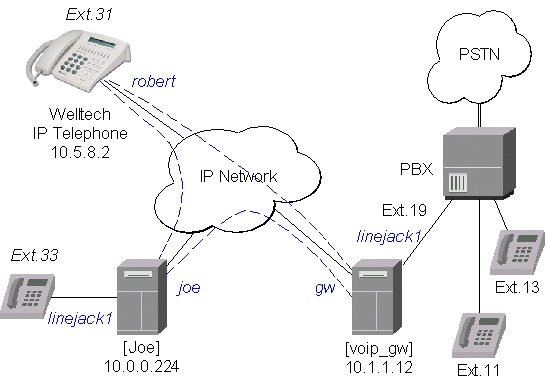
Setting up the MikroTik IP Telephone
The QuickNet LineJACK or PhoneJACK card and the MikroTik RouterOS telephony package should be installed in the MikroTik router (IP telephone) 10.0.0.224x. An analog telephone should be connected to the 'phone' port of the QuickNet card. If you pick up the handset, a dialtone should be heard.The basic telephony configuration should be as follows:
- Add a voip voice port to the /ip telephony voice-port voip
for each of the devices you want to call, or want to receive calls from,
i.e., (the IP telephony gateway 10.1.1.12 and the Welltech IP telephone 10.5.8.2):
[admin@Joe] ip telephony voice-port voip> add name=gw remote-address=10.1.1.12
[admin@Joe] ip telephony voice-port voip> add name=rob remote-address=10.5.8.2
[admin@Joe] ip telephony voice-port voip> print
Flags: X - disabled, D - dynamic, R - registered
  #    NAME      AUTODIAL REMOTE-ADDRESS  JITTER-BUFFER PREFERED-CODEC  SIL FAS
  0    gw                 10.1.1.12       100ms         none            no  yes
  1    rob                10.5.8.2        100ms         none            no  yes
[admin@Joe] ip telephony voice-port voip>
You should have three vioce ports now:[admin@Joe] ip telephony voice-port> print Flags: X - disabled # NAME TYPE AUTODIAL 0 linejack1 linejack 1 gw voip 2 rob voip [admin@Joe] ip telephony voice-port>
- Add a at least one unique number to the /ip telephony numbers for each voice port.
This number will be used to call that port:
[admin@Joe] ip telephony numbers> add dst-pattern=31 voice-port=rob
[admin@Joe] ip telephony numbers> add dst-pattern=33 voice-port=linejack1
[admin@Joe] ip telephony numbers> add dst-pattern=1. voice-port=gw prefix=1
[admin@Joe] ip telephony numbers> print
Flags: I - invalid, X - disabled, D - dynamic, R - registered
  #     DST-PATTERN             VOICE-PORT              PREFIX
  0     31                          rob                 31
  1     33                          linejack1
  2     1.                          gw                  1
[admin@Joe] ip telephony numbers>
Here, the dst-pattern=31 is to call the Welltech IP Telephone, if the number '31' is dialed on the dialpad.
The dst-pattern=33 is to ring the local telephone, if a call for number '33' is received over the network.
Anything starting with digit '1' would be sent over to the IP Telephony gateway.
Making calls from the IP telephone 10.0.0.224:
- To call the IP telephone 10.5.8.2, it is enough to lift the handset and dial the number "31".
- To call the PBX extension 13, it is enough to lift the handset and dial the number "13".
After establishing the connection with '13', the voice port monitor shows:
[admin@Joe] ip telephony voice-port linejack> monitor linejack
               status: connection
                 port: phone
            direction: port-to-ip
          line-status: unplugged
         phone-number: 13
    remote-party-name: PBX_Line [10.1.1.12]
                codec: G.723.1-6.3k/hw
             duration: 16s

[admin@Joe] ip telephony voice-port linejack>
Use the telephony logging feature to debug your setup.
Setting up the IP Telephony Gateway
QuickNet LineJACK, Voicetronix, Zaptel Wildcard or ISDN (see the appropriate manual) card and the MikroTik RouterOS telephony package should be installed in the MikroTik router (IP telephony gateway) 10.1.1.12. A PBX line should be connected to the 'line' port of the card. For LineJACK card the LED next to the 'line' port should be green, not red.
The IP telephony gateway [voip_gw] requires the following configuration:
- Set the regional setting to match our PBX. The mikrotik seems to be best suited:
[admin@voip_gw] ip telephony voice-port linejack> set linejack1 region=mikrotik [admin@voip_gw] ip telephony voice-port linejack> print Flags: X - disabled 0 name="linejack1" autodial="" region=mikrotik playback-volume=0 record-volume=0 ring-cadence="++-++--- ++-++---" agc-on-playback=no agc-on-record=no aec=yes aec-tail-length=short aec-nlp-threshold=low aec-attenuation-scaling=4 aec-attenuation-boost=0 software-aec=no detect-cpt=yes [admin@voip_gw] ip telephony voice-port linejack> - Add a voip voice port to the /ip telephony voice-port voip
for each of the devices you want to call, or want to receive calls from,
i.e., (the IP telephone 10.0.0.224 and the Welltech IP telephone 10.5.8.2):
[admin@voip_gw] ip telephony voice-port voip> add name=joe \
\... remote-address=10.0.0.224
[admin@voip_gw] ip telephony voice-port voip> add name=rob \
\... remote-address=10.5.8.2 prefered-codec=G.723.1-6.3k/hw
[admin@voip_gw] ip telephony voice-port voip> print
Flags: X - disabled, D - dynamic, R - registered
  #    NAME      AUTODIAL REMOTE-ADDRESS  JITTER-BUFFER PREFERED-CODEC  SIL FAS
  0    joe                10.0.0.224      100ms         none            no yes
  1    rob                10.5.8.2        100ms         G.723.1-6.3k/hw no yes
[admin@voip_gw] ip telephony voice-port voip>
- Add number records to the /ip telephony numbers, so you are able to
make calls:
[admin@voip_gw] ip telephony numbers> add dst-pattern=31 voice-port=rob prefix=31
[admin@voip_gw] ip telephony numbers> add dst-pattern=33 voice-port=joe prefix=33
[admin@voip_gw] ip telephony numbers> add dst-pattern=1. voice-port=linejack1 \
\... prefix=1
[admin@voip_gw] ip telephony numbers> print
Flags: I - invalid, X - disabled, D - dynamic, R - registered
  #     DST-PATTERN             VOICE-PORT              PREFIX
  0     31                          rob                 31
  1     33                          joe                 33
  2     1.                          linejack1           1
[admin@voip_gw] ip telephony numbers>
Making calls through the IP telephony gateway:
- To dial the IP telephone 10.0.0.224 from the office PBX line, the extension number 19 should be dialed,
and, after the dial tone has been received, the number 33 should be entered. Thus, the telephone [Joe]
is ringed.
After establishing the voice connection with '33' (the call has been answered), the voice port monitor shows:
[admin@voip_gw] ip telephony voice-port linejack> monitor linejack1 status: connection port: line direction: port-to-ip line-status: plugged phone-number: 33 remote-party-name: linejack1 [10.0.0.224] codec: G.723.1-6.3k/hw duration: 1m46s [admin@voip_gw] ip telephony voice-port linejack> - To dial the IP telephone 10.5.8.2 from the office PBX line, the extension number 19 should be dialed, and, after the dial tone has been received, the number 31 should be entered.
Setting up the Welltech IP Telephone
Please follow the documentation from www.welltech.com.tw on how to set up the Welltech LAN Phone 101. Here we give just brief recommendations:
- We recommend to upgrade the Welltech LAN Phone 101 with the latest application software.
Telnet to the phone and check what you have, for example:
usr/config$ rom -print Download Method : TFTP Server Address : 10.5.8.1 Hardware Ver. : 4.0 Boot Rom : nblp-boot.102a Application Rom : wtlp.108h DSP App : 48302ce3.127 DSP Kernel : 48302ck.127 DSP Test Code : 483cbit.bin Ringback Tone : wg-ringbacktone.100 Hold Tone : wg-holdtone10s.100 Ringing Tone1 : ringlow.bin Ringing Tone2 : ringmid.bin Ringing Tone3 : ringhi.bin usr/config$ - Check if you have the codecs arranged in the desired order:
usr/config$ voice -print Voice codec setting relate information Sending packet size : G.723.1 : 30 ms G.711A : 20 ms G.711U : 20 ms G.729A : 20 ms G.729 : 20 ms Priority order codec : g7231 g711a g711u g729a g729 Volume levels : voice volume : 54 input gain : 26 dtmf volume : 23 Silence suppression & CNG: G.723.1 : Off Echo canceller : On JitterBuffer Min Delay : 90 JitterBuffer Max Delay : 150 usr/config$ - Make sure you have set the H.323 operation mode to phone to phone (P2P),
not gatekeeper (GK):
usr/config$ h323 -print H.323 stack relate information RAS mode : Non-GK mode Registered e164 : 31 Registered H323 ID : Rob RTP port : 16384 H.245 port : 16640 Allocated port range : start port : 1024 end port : 65535 Response timeOut : 5 Connect timeOut : 5000 usr/config$ - Add the gateway's address to the phonebook:
usr/config$ pbook -add name gw ip 10.1.1.12
usr/config$
This may take a few seconds, please wait....

Commit to flash memory ok!

usr/config$ pbook -print
index   Name                 IP                    E164
======================================================================
1       gw                   10.1.1.12
----------------------------------------------------------------------
usr/config$
Making calls from the IP telephone 10.5.8.2:
- Just lift the handset and dial '11', or '13' fo the PBX extensions.
- Dial '33' for [Joe]. The call request will be sent to the gateway 10.1.1.12,
where it will be forwarded to [Joe].
If you want to call [Joe] directly, add a phonebook record for it:
usr/config$ pbook -add name Joe ip 10.0.0.224 e164 33
Use the telephony logging feature on the gateway to debug your setup.
Setting up the MikroTik Router and CISCO Router
Here are some hints on how to get working configuration for telephony calls between CISCO and MikroTik router.Tested on:
- MT: 2.4.1
- CISCO: 1750
- G.729a codec MUST be disabled (otherwise connections are not possible at all)!!!
/ip telephony codec disable G.729A-8k/sw
- G.711-ALaw codec should not be used (in some cases there is no sound)
/ip telephony codec disable "G.711-ALaw-64k/sw G.711-ALaw-64k/hw"
- Fast start has to be used (otherwise no ring-back tone and problems with codec negotiation)
/ip telephony voice-port set cisco fast-start=yes
- Telephone number we want to call to must be sent to Cisco, for example
/ip telephony numbers add destination-pattern=101 voice-port=cisco prefix=101
- Telephone number, cisco will call us, must be assigned to some voice port, for example,
/ip telephony numbers add destination-pattern=098 voice-port=linejack
Configuration on the CISCO side:
- IP routing has to be enabled
ip routing
- Default values for fast start can be used
voice service pots default h323 call start exit voice service voip default h323 call start exit - Enable opening of RTP streams
voice rtp send-recv
- Assign some E.164 number for local telephone, for example, 101 to port 0/0
dial-peer voice 1 pots destination-pattern 101 port 0/0 exit - create preferred codec listing
voice class codec codec_class_number
    codec preference 1 g711ulaw
    codec preference 2 g723r63
    exit
NOTE: g723r53 codec can be used, too - Tell, that some foreign E.164 telephone number can be reached by calling to some IP address,
for example, 098 by calling to 10.0.0.98
dial-peer voice 11 voip
    destination-pattern 098
    session target ipv4:10.0.0.98
    voice-class codec codec_class_number
    exit
NOTE: instead of codec class, one specified codec could be specified:codec g711ulaw
For reference, following is an exported CISCO configuration, that works:
!
version 12.1
no service single-slot-reload-enable
service timestamps debug uptime
service timestamps log uptime
no service password-encryption
!
hostname Router
!
logging rate-limit console 10 except errors
enable secret 5 $1$bTMC$nDGl9/n/pc3OMbtWxADMg1
enable password 123
!
memory-size iomem 25
ip subnet-zero
no ip finger
!
call rsvp-sync
voice rtp send-recv
!
voice class codec 1
 codec preference 1 g711ulaw
 codec preference 2 g723r63
!
interface FastEthernet0
 ip address 10.0.0.101 255.255.255.0
 no ip mroute-cache
 speed auto
 half-duplex
!
ip classless
ip route 0.0.0.0 0.0.0.0 10.0.0.1
no ip http server
!
dialer-list 1 protocol ip permit
dialer-list 1 protocol ipx permit
!
voice-port 0/0
!
voice-port 0/1
!
voice-port 2/0
!
voice-port 2/1
!
dial-peer voice 1 pots
 destination-pattern 101
 port 0/0
!
dial-peer voice 97 voip
 destination-pattern 097
 session target ipv4:10.0.0.97
 codec g711ulaw
!
dial-peer voice 98 voip
 destination-pattern 098
 voice-class codec 1
 session target ipv4:10.0.0.98
!
!
line con 0
 transport input none
line aux 0
line vty 0 4
 password 123
 login
!
end
Setting up PBX to PBX Connection over an IP Network
To interconnect two telephone switchboards (PBX) over an IP network, two IP telephony gateways should be configured.
The setup is shown in the following diagram:
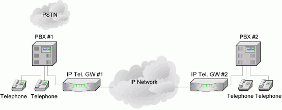
We want to be able to use make calls from local telephones of one PBX to local telephones or external lines of the other PBX.
Assume that:
- The IP telephony gateway #1 has IP address 10.0.0.182, and the name of the Voicetronix�s first line is �vctx1�.
- The IP telephony gateway #2 has IP address 10.0.0.183, and the name of the
Voicetronix�s first line is �vctx1�.
The IP telephony configuration should be as follows:
- IP telephony gateway #1 should have
/ip telephony voice-port voip
add name=gw2 remote-address=10.0.0.183
/ip telephony numbers
add dst-pattern=1.. voice-port=gw2 prefix=2
add dst-pattern=2.. voice-port=vctx1 prefix=1
- IP telephony gateway #2 should have
/ip telephony voice-port voip
add name=gw1 remote-address=10.0.0.182
/ip telephony numbers
add dst-pattern=2.. voice-port=vctx1 prefix=1
add dst-pattern=1.. voice-port=gw1 prefix=2
To dial from the main office PBX#1 any extension of the remote office PBX#2, the extension with the connected gateway at PBX#1 should be dialed first. Then, after the dial tone of the gateway#1 is received, the remote extension number should be dialed.
To dial from the main office PBX#2 any extension of the remote office PBX#1, the actions are the same as in first situation.
Additional Resources
IP Telephony Online© Copyright 1999-2003, MikroTik