Queue Management and Bandwidth Control
Document revision 12-Oct-2001
This document applies to the MikroTik RouterOS V2.4
The MikroTik RouterOS supports the following queuing mechanisms:
The queuing can be used for limiting the bandwidth for certain IP addresses, protocols or ports. The queuing is performed for packets leaving the router through an interface. It means that the queues should always be configured on the outgoing interface regarding the traffic flow. If there is a desire to limit the traffic arriving at the router, then it should be done at the outgoing interface of some other router.
References on Class-Based Queuing (CBQ) can be found at http://www.aciri.org/floyd/cbq.html
Queues can be added using the add command:
[MikroTik] ip queue> add interface=ether2 queue=red limit-at=64000 bounded=yes
[MikroTik] ip queue> print
Flags: X - disabled, I - invalid
  0   src-address=0.0.0.0/0:0-65535 dst-address=0.0.0.0/0:0-65535
      protocol=all queue=red limit-at=64000 max-burst=20 bounded=yes priority=8
      weight=1 allot=1538 bfifo-limit=10000 pfifo-limit=100 red-limit=60
      red-min-threshold=10 red-max-threshold=50 red-burst=20 interface=ether2

[MikroTik] ip queue>
Argument description:
allot - Number of bytes allocated for the bandwidth. Should not be less than the MTU for the interface.
bfifo-limit - BFIFO queue limit. Maximum packet number that queue can hold.
bounded - Queue is bounded. If set to 'yes', the queue can not occupy bandwidth of other queues. If set to 'no', the queue would use over the allocated bandwith whenever possible. Only in case when other queues (the actual queues) are getting too long and a connection is not being satisfied, then the 'not-bounded' queues would be limited at their allocated bandwidth.
dst-address - Destination IP address. Can be in the form a.b.c.d/n:p1[-p2], that consists of the IP address, number of bits in the network mask, and the port or port range.
dst-netmask - Destination netmask
dst-port - Destination port number or range (0-65535). '0' means all ports.
interface - Interface which packet leaves. Queues work only for packets leaving the interface.
limit-at - Maximum stream bandwidth (bits/s). '0' means no limit (default for the interface).
max-burst - Maximal number of packets allowed for bursts of packets when there are no packets in the queue. Set to '0' for no burst.
pfifo-limit - PFIFO queue limit. Maximum byte number that queue can hold.
priority - Flow priority (1..15)
protocol - Protocol
queue - Queue type (see explanation below)
red-burst - RED burst. Number of packets allowed for bursts of packets when there are no packets in the queue. The minimum value that can be used here is equal to the value of 'red-min-threshold'.
red-limit - RED queue limit
red-min-threshold - RED minimum threshold. Before this value is achieved no packets will be thrown away.
red-max-threshold - RED maximum threshold. When this value is achieved the queue will throw away the packets using maximum probability, where this probability is a function of the average queue size.
src-address - Source IP address. Can be in the form a.b.c.d/n:p1[-p2], that consists of the IP address, number of bits in the network mask, and the port or port range.
src-netmask - Source netmask
src-port - Source port number or range (0-65535). '0' means all ports.
weight - Flow weight
Queue types:
Queue rules are processed in the order they appear in the /ip queue print list. If some packet matches the queue rule, then the queuing mechanism specified in that rule is applied to it, and no more rules are processed for that packet.
You can group several networks together and have one queue for them, if a common network mask can be found for the networks. For example, networks 10.0.128.0/24 and 10.0.129.0/24 can be grouped together using a common network address/mask 10.0.128.0/22
Queue Applications
One of the ways to avoid network traffic ‘jams’ is usage of traffic shaping in large networks.
Traffic shaping and bandwidth allocation is implemented in the MikroTik RouterOS as queuing mechanism.
Thus, the network administrator is able to allocate a definite portion of the total bandwidth
and grant it to a particular network segment or interface.
Also the bandwidth of particular nodes can be limited by using this mechanism.
Further on, several examples of using bandwidth management are given arranged according to complexity:
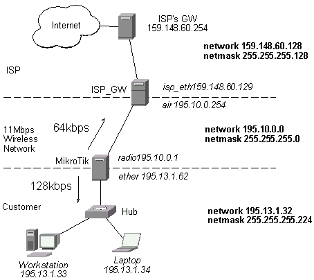
Assume we want to emulate a 128k download and 64k upload line connecting IP network 195.13.1.32/27. The network is served through the interface 'ether' of customer's router The basic network setup is in the following diagram:
The IP addresses and routes of the MikroTik router are as follows:
[MikroTik] > ip address print
Flags: X - disabled, I - invalid, D - dynamic
  #   ADDRESS            NETWORK         BROADCAST       INTERFACE
  0   195.10.0.1/24      195.10.0.0      195.10.0.255    radio
  1   195.13.1.62/27     195.13.1.32     195.13.1.63     ether
[MikroTik] > ip route print detail
Flags: X - disabled, I - invalid, D - dynamic, R - rejected
  0    dst-address=0.0.0.0/0 gateway=195.10.0.254 nexthop-state=A
       preferred-source=0.0.0.0 interface=radio distance=1 type=static

  1 D  dst-address=195.13.1.32/27 gateway=0.0.0.0 nexthop-state=A
       preferred-source=195.13.1.62 interface=ether distance=0 type=connect

  2 D  dst-address=195.10.0.0/24 gateway=0.0.0.0 nexthop-state=A
       preferred-source=195.10.0.1 interface=radio distance=0 type=connect

[MikroTik] >
It is enough to add two queues at the customer's router:
[MikroTik] ip queue>
add dst-address 195.13.1.32/27 interface ether \
queue red limit-at 128000 max-burst 0 bounded yes
add src-address 195.13.1.32/27 interface radio \
queue red limit-at 64000 max-burst 0 bounded yes
[MikroTik] ip queue> print
Flags: X - disabled, I - invalid
  0   src-address=0.0.0.0/0:0-65535 dst-address=195.13.1.32/27:0-65535
      protocol=all queue=red limit-at=128000 max-burst=0 bounded=yes priority=8
      weight=1 allot=1538 bfifo-limit=10000 pfifo-limit=100 red-limit=60
      red-min-threshold=10 red-max-threshold=50 red-burst=20 interface=ether

  1   src-address=195.13.1.32/27:0-65535 dst-address=0.0.0.0/0:0-65535
      protocol=all queue=red limit-at=64000 max-burst=0 bounded=yes priority=8
      weight=1 allot=1538 bfifo-limit=10000 pfifo-limit=100 red-limit=60
      red-min-threshold=10 red-max-threshold=50 red-burst=20 interface=radio

[MikroTik] ip queue>
Leave all other parameters as set by default. The limit is approximately 128kbps going to the client's network and 64kbps leaving the client's network. No burst of the packets is allowed. Please note, that each queue has been added for the outgoing interface regarding the traffic flow.
If local address space 192.168.0.0/24 and masquerading are used for the client computers in the previous example setup, then the outgoing traffic has masqueraded source address 195.10.0.1, i.e., the outgoing packets have external address of the router as the source. The network diagram is as follows:
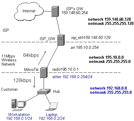
The IP addresses, routes, and masquerading firewall rule of the MikroTik router are as follows:
[MikroTik] > ip address print
Flags: X - disabled, I - invalid, D - dynamic
  #   ADDRESS            NETWORK         BROADCAST       INTERFACE
  0   195.10.0.1/24      195.10.0.0      195.10.0.255    radio
  1   192.168.0.254/24   192.168.0.0     192.168.0.255   ether
[MikroTik] > ip route print detail
Flags: X - disabled, I - invalid, D - dynamic, R - rejected
  0    dst-address=0.0.0.0/0 gateway=195.10.0.254 nexthop-state=A
       preferred-source=0.0.0.0 interface=radio distance=1 type=static

  1 D  dst-address=195.10.0.0/24 gateway=0.0.0.0 nexthop-state=A
       preferred-source=195.10.0.1 interface=radio distance=0 type=connect

  2 D  dst-address=192.168.0.0/24 gateway=0.0.0.0 nexthop-state=A
       preferred-source=192.168.0.254 interface=ether distance=0 type=connect

[MikroTik] > ip firewall rule forward print
Flags: X - disabled, I - invalid
  0   protocol=all src-address=192.168.0.254/24:0-65535
      dst-address=0.0.0.0/0:0-65535 interface=radio action=masq tcp-options=all
      log=no

[MikroTik] >
The queuing rule for incoming traffic should match the customer's local addresses, whereas the rule for outgoing traffic should match the router's external address as the source address:
[MikroTik] ip queue>
add dst-address 192.168.0.0/24 interface ether \
queue red limit-at 128000 max-burst 0 bounded yes
add src-address 195.10.0.1/32 interface radio \
queue red limit-at 64000 max-burst 0 bounded yes
[MikroTik] ip queue> print
Flags: X - disabled, I - invalid
  0   src-address=0.0.0.0/0:0-65535 dst-address=192.168.0.0/24:0-65535
      protocol=all queue=red limit-at=128000 max-burst=0 bounded=yes priority=8
      weight=1 allot=1538 bfifo-limit=10000 pfifo-limit=100 red-limit=60
      red-min-threshold=10 red-max-threshold=50 red-burst=20 interface=ether

  1   src-address=195.10.0.1/32:0-65535 dst-address=0.0.0.0/0:0-65535
      protocol=all queue=red limit-at=64000 max-burst=0 bounded=yes priority=8
      weight=1 allot=1538 bfifo-limit=10000 pfifo-limit=100 red-limit=60
      red-min-threshold=10 red-max-threshold=50 red-burst=20 interface=radio

[MikroTik] ip queue>
Let us assume that for administrative purposes, we want to contact the MikroTik router without being affected by the bandwidth limitation. Then additional rule(s) having no limitation should be added before the limiting one(s). For example, we want no limitation to host 159.148.60.200. The queue rule should be added as follows:
[MikroTik] ip queue>
add src-address 195.10.0.1/32 dst-address 159.148.60.200/32 interface radio
[MikroTik] ip queue> pr
Flags: X - disabled, I - invalid
  0   src-address=0.0.0.0/0:0-65535 dst-address=192.168.0.0/24:0-65535
      protocol=all queue=red limit-at=128000 max-burst=0 bounded=yes priority=8
      weight=1 allot=1538 bfifo-limit=10000 pfifo-limit=100 red-limit=60
      red-min-threshold=10 red-max-threshold=50 red-burst=20 interface=ether

  1   src-address=195.10.0.1/32:0-65535 dst-address=0.0.0.0/0:0-65535
      protocol=all queue=red limit-at=64000 max-burst=0 bounded=yes priority=8
      weight=1 allot=1538 bfifo-limit=10000 pfifo-limit=100 red-limit=60
      red-min-threshold=10 red-max-threshold=50 red-burst=20 interface=radio

  2   src-address=195.10.0.1/32:0-65535 dst-address=159.148.60.200/32:0-65535
      protocol=all queue=none limit-at=0 max-burst=20 bounded=no priority=8
      weight=1 allot=1538 bfifo-limit=10000 pfifo-limit=100 red-limit=60
      red-min-threshold=10 red-max-threshold=50 red-burst=20 interface=radio

[MikroTik] ip queue>
Move the rule #2 to the top:
[MikroTik] ip queue> move 2 0
[MikroTik] ip queue> print columns="src-address dst-address interface " brief
Flags: X - disabled, I - invalid
  #   SRC-ADDRESS                    DST-ADDRESS                    INTERFACE
  0   195.10.0.1/32:0-65535          159.148.60.200/32:0-65535      radio
  1   0.0.0.0/0:0-65535              192.168.0.0/24:0-65535         ether
  2   195.10.0.1/32:0-65535          0.0.0.0/0:0-65535              radio
[MikroTik] ip queue>
The first rule means no limitation to the host 159.148.60.200, whereas the second two rules limit customer's incoming and outgoing traffic, respectively.